Continue to Site

Welcome to EDAboard.com

Welcome to our site! EDAboard.com is an international Electronics Discussion Forum focused on EDA software, circuits, schematics, books, theory, papers, asic, pld, 8051, DSP, Network, RF, Analog Design, PCB, Service Manuals... and a whole lot more! To participate you need to register. Registration is free. Click here to register now.

LCD code works only in debugging mode not out of debugging.

Status
Not open for further replies.

anand003

Junior Member level 2
Joined
Feb 18, 2010
Messages
24
Helped
1
Reputation
2
Reaction score
1
Trophy points
1,283
Location
bangalore
Activity points
1,422
Hi,

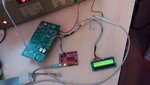
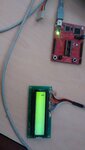
I need some help to fix code issues on LCD 16X2 which I have implemented for MSP430F5132 controller.(see the attachment ) . And it is seem to be working only while debugging, i.e it is displaying characters while debugging not after coming out from debugging.

I guess the issue is related to either the clock or with delays in the program. Anyways attaching the code with this query ,this will give more light to understand the problem.


Note: I as mentioned earlier, the code works in debugging mode.

A little help to solve the issue would be appreciated.
:-:)-(


Thanks in advance.

Regards

Anand.
 

Attachments

  • version2.rar
    7 KB · Views: 101

when running in debugging mode the system tends to run much slower than when not debugging so I would guess you are sending data to the LCD too fast

LCDs can be very slow devices so one usually has to put delays between writing data, e.g. this is writing a nibble on a PIC24FJ256GB110 running at 32MHz
Code:
// Write a nibble to the LCD
// may have to adjust delays to suit the processor and clock
void lcdNibble(int n)
{
    int lcd=LCDdata;

	__delay_us(800); 
  	LCDdata = (lcd&0xfff0) | ((n & 0x0f));			// send out lower Nibble
  	Nop();					// Wait E Pulse width time (min 230ns)
	Nop();
	Nop();
	Nop();
	Nop();
	Nop();
	Nop();
	Nop();
	Nop();

  LCDstatus.E=1;					// take clock E high 
	Nop();					// Wait E Pulse width time (min 230ns)
	Nop();
	Nop();
	Nop();
	Nop();
	Nop();
	Nop();
	Nop();
	Nop();

    LCDstatus.E=0;
 	__delay_us(800); 
 }

// Write a Control Command to the LCD
// This is written as two nibbles
void lcdCmd(int c)
{
 	LCDstatus.RS=0;			        // Take RS pin low for command
	lcdNibble(c >>4);		        // Makeup Upper Nibble
	lcdNibble(c);			        // Makeup Lower Nibble
}

I uisually make the delays long, e.g. 5mSecs then reduce them until I get a stable working version
 
hello horace1,

Thanks for replying

Even though I tried playing with delays, I didn't tried delaying enable signal will try that and update
 

I have tried with nop function and delays there seems to be no success. I am attaching picture to understand the problem better the pic 1 while working in debugging ( even in continuous run ) but fails to run in normal condition without emulator connected. Pic2
 

Attachments

  • PIC1.jpeg
    PIC1.jpeg
    461.4 KB · Views: 113
  • PIC2.jpeg
    PIC2.jpeg
    432.1 KB · Views: 117

I think u should revise the timing requirement(Bus Timing Characteristics) in pages 49 & 52
here https://www.sparkfun.com/datasheets/LCD/HD44780.pdf & compare them to the timing used in your code.
Also u should revise timing needed during initialization in pages 45 & 46
(also LCD intial. here can be more explanatory here
**broken link removed**
**broken link removed**)
 
1. It works in debug mode, which shows that the data timing and bus timing is correct!!.( further to confirm will cross verify).

2.If the debug mode and the normal mode works same clock speed ..should work in both conditions....!!!??
 

Status
Not open for further replies.

Similar threads

Part and Inventory Search

Welcome to EDABoard.com

Sponsor

Back
Top