Continue to Site

Welcome to EDAboard.com

Welcome to our site! EDAboard.com is an international Electronics Discussion Forum focused on EDA software, circuits, schematics, books, theory, papers, asic, pld, 8051, DSP, Network, RF, Analog Design, PCB, Service Manuals... and a whole lot more! To participate you need to register. Registration is free. Click here to register now.

[SOLVED] choosing right mosfet VDS SSR

Status
Not open for further replies.

Electro nS

Full Member level 6
Joined
Mar 9, 2013
Messages
324
Helped
49
Reputation
98
Reaction score
48
Trophy points
1,308
Activity points
3,818
hi

i have learned through experiments in power electronics and working with N channel mosfets
that when you design a converter/controller in half/full bridge topology , you choose the VDS rating to be 2x Vcc (for inductive loads) , because of transients and such staff.

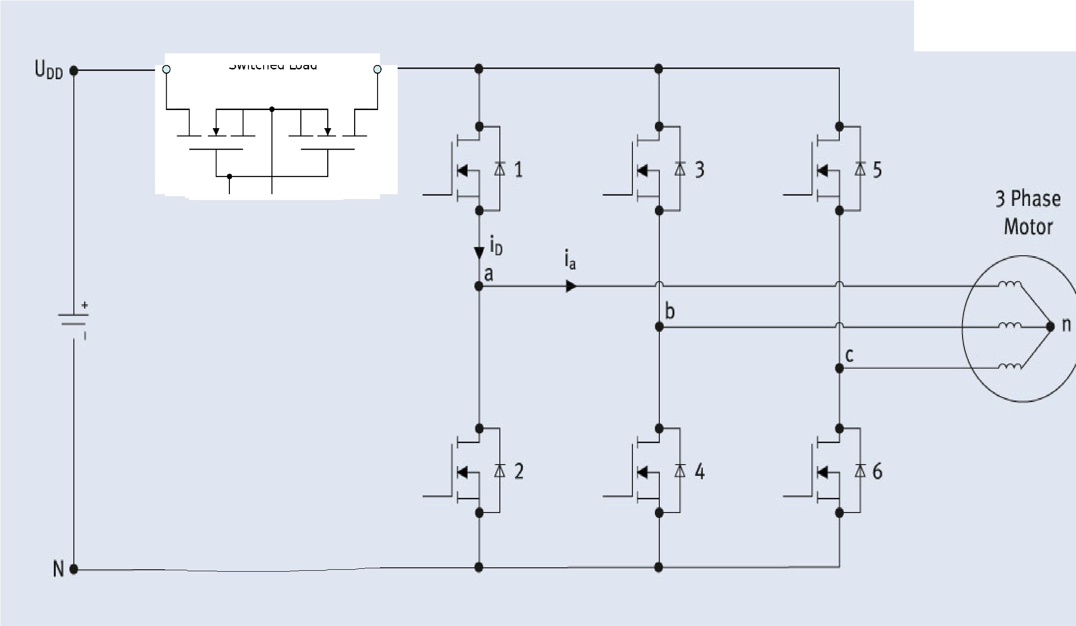
now my question do i have to use the same overrating if i am using this mosfet in Solid state relay configuration ?? here i will turn on once the device (ex 3 phase inverter) is on , and off after operation is finished , so now frequent switching on this device ...
so does the mosfet in the SSR effects by the transisent as the mosfets in the bridge ??? should all of them have the same Vds ??

info: circuit voltage is 24-28v , mosfets in brige are 60v vds , in ssr i am "hoping" to use 40v mosfet , please advise !!! see attached circuit


I think when the bridge FETs change over, the 2 X 24 = 48V is routed via their internal flyback diodes back into the supply. If there is enough decoupling then while there is a current pulse there would be little voltage. Putting another device in series upsets this. So with enough decoupling on the motor side and perhaps a capacitor ACROSS your FET then a 40V FET could be used.
Frank
 
This requires a detailed analysis of your driver and output transition times and slew rates thru the CISS and COSS regions of each device.

The lower the output RdsOn, the better, but more gate current needed.

Look at the RC time constants during this transition time and compare Each Stage's dampening factor, RL/Rs from coil Rs to output RdsOn to each previous stage . don't be surprised if the impedance gain of the Switch resistance to the next stage to the coil resistance is only 10% for a dampening factor of 10. (More or less) Then learn how to control dead-time around 1-2us to avoid shoot-thru if the core saturates for many reason. look at methods for,current limiting on each cycle.
Then compare costs with a 3 phase Mosfet bridge.


Sorry no more time today.
 
when the SSR is on , it should appear as a short circuit right (2-5mohm mosfet) ?? so during this time anything happening in the bridge , spikes , switching whatever ... should not affect it , because a value of current may pass uninterrupted ..

The way i understand it , when mosfets switch and disrupt current flow with an inductive load this creates the voltage transisents . so for the 2 mosfets in SSR ( i think i will add TVS diodes across each from drain to source) , 40v should be suffcient .

maybe i should try it after all and test
 

Primarly I don't understand the circuit's purpose.

Regarding voltage ratings, the bus voltage of the three phase bridge is effectively unclamped, turning the input switch off while the load is sourcing current can force some of the switch transistors into avalanche breakdown whatever it's voltage rating is.

To clarify :::: the purpose of the circuit is reverse battery protection, instead of using a mechanical relay. , it will be turn on once and will NOT be turned off while the load is sourcing or sinking current , only when power supply is off the signal to the gate is off and relay turns off , this happens after motor have stopped .
So in this case please answer : does the switch see any spike , is it safe to use a 40v mosfet , should TVS diodes be added and where ??
thanks and regrads
 

the purpose of the circuit is reverse battery protection, instead of using a mechanical relay. , it will be turn on once and will NOT be turned off while the load is sourcing or sinking current , only when power supply is off the signal to the gate is off and relay turns off , this happens after motor have stopped .
If so, why are you asking about "spikes"? There are no spikes across a closed switch. If you're no so sure at all, MOSFET avalanche energy rating can typically keep up with TVS diodes.
 
Status
Not open for further replies.

Similar threads

Part and Inventory Search

Welcome to EDABoard.com

Sponsor

Back
Top