Continue to Site

Welcome to EDAboard.com

Welcome to our site! EDAboard.com is an international Electronics Discussion Forum focused on EDA software, circuits, schematics, books, theory, papers, asic, pld, 8051, DSP, Network, RF, Analog Design, PCB, Service Manuals... and a whole lot more! To participate you need to register. Registration is free. Click here to register now.

Pierce oscilaltor level adjustment

Status
Not open for further replies.

neazoi

Advanced Member level 6
Joined
Jan 5, 2008
Messages
4,122
Helped
13
Reputation
26
Reaction score
15
Trophy points
1,318
Location
Greece
Activity points
36,951
Hello,
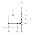
I have made this oscillator and it outputs a low distortion sinewave at all HF feqencies (1M oscilloscope).
The "problem" is that the variable capacitor has to be adjusted if the crystal is changed, for a clean sinewave (or constant signal level) at the output, because of the different characteristics of different crystals and when different frequencies are needed.

I would like to hear your proposals on how to somehow make this capacitance auto adjusted, so that the output level remains constant with different crystals/frequencies.

A thought I had, was to somehow detect the output signal level. If it is lower than a preset threshold, then I perform an action to adjust the capacitor accordingly.

Any thoughts will be appreciaded, but keep in mind that the solution has to be kept simple.
 

Attachments

  • untitled.jpg
    untitled.jpg
    6.1 KB · Views: 46


Re: Pierce oscillator level adjustment

Varicaps can be made to change capacitance with voltage, but this is just a VCXO.

The peak amplitude is not always found at the desired centre frequency, but may be calibrated by test ref f.

the CMOS pi network is preferred to your design as frequency does not shift with load.

https://upload.wikimedia.org/wikipe...tor.svg/220px-Pierce_Quarz_Oszillator.svg.png
Thank you,
Indeed the altering of the capacitance in that place changes a bit the frequency of the crystal, but in my application (qrp cheap transmitter) this is not too much of a problem, since frequency stability is more important than accurate frequency. Amplitude stability is important if one wants to output the same output power at all HF bands, and this is what I am trying to accomplish.
This can be accomplished by an AGC amplifier, but I want to accomplish it in the oscillator, because the capacitor setting does not only influence the output power of the oscillator but also the sinewave distortion.
Based on my experiments, the capacitor should be set at the lowest output signal that starts reliably the oscillator. This also gives the lowest distortion sinewave.
It is that point that I need to keep constant when changing different crystals.
I have found some solutions, some make use of the buffer amplifiers, others do it with adjusting the gain of a dual gate mosfet.
https://www.qsl.net/va3iul/Homebrew...s/18MHz_very_stable_constant_amplitude_LO.gif
https://www.qsl.net/va3iul/Homebrew_RF_Circuit_Design_Ideas/11MHz-34MHz_VCO_Const_Amplitude.gif
https://www.qsl.net/va3iul/Homebrew_RF_Circuit_Design_Ideas/5MHz_Amplitude_Stabilized_LO.gif
https://www.qsl.net/va3iul/Homebrew_RF_Circuit_Design_Ideas/LC_LO_Amplitude_Stabilization.gif
I would like your comments please.
 

If your crystals have different "activity", then the oscillator has to be designed with lots of loop gain, so the output level becomes dependent on the Vcc or some hard limiting only and not any small non-linearity within the amplifier.
The crystal oscillates when it looks inductive and it has a capacitor at each to earth to make a centre tap (for phase reversal), the capacitor at one end is seen, the other might be created by stray capacitance, so you could try putting on a small capacitor across the drain load resistor to increase this.
Frank
 
  • Like
Reactions: neazoi

    neazoi

    Points: 2
    Helpful Answer Positive Rating
For QRP you probably use only one frequency band with final set of crystals. Crystals are usually selected with rotary switch and corresponding tuning elements can be selected in the same way.
 

If your crystals have different "activity", then the oscillator has to be designed with lots of loop gain, so the output level becomes dependent on the Vcc or some hard limiting only and not any small non-linearity within the amplifier.
The crystal oscillates when it looks inductive and it has a capacitor at each to earth to make a centre tap (for phase reversal), the capacitor at one end is seen, the other might be created by stray capacitance, so you could try putting on a small capacitor across the drain load resistor to increase this.
Frank
I am a bit confused of what you say. Do you refer to the capacitor in the circuit I posted or a synthetic capacitor (2 caps center tapped to earth) parallel to the crystal?
How does it relate to the variable capacitor automatic adjustment in the circuit I posted?

Most of the ALC circuits I have seen, make use of a diode detector at the oscillator output that charges a capacitor to drive an opamp comparator os another transistor stage, which in turn alters some of the characteristics of the circuit (resistances in a bjt oscillator usually).

I have tried including a diode rectifier and capacitor at the oscillator output and replacing the variable cap with a varicap in series with a fixed cap. It did not work as expected, but a voltage applied between the varicap and the fixed capacitor did the trick.
I just need this voltage to be somehow related to the oscillator output, but it seems the varicap draws too much current and the reservoir capacitor in the rectifier discharges too quickly.
 

Usually the variable capacitor in the pierce (or other crystal oscillator) circuit has the purpose of fine-tuning (or "pulling") the oscillator frequency. The output amplitude variation would be considered as a side effect.

All four oscillator circuits in your links, despite of their different topology, implement level control by manipulating the oscillator DC bias point.
 
  • Like
Reactions: neazoi

    neazoi

    Points: 2
    Helpful Answer Positive Rating
there are a number of papers out there that add an automatic level control to the oscillator to limit how much the transistor goes into compression. You could try that.

One of the first pieces of test equipment Hewllet and Packard made in their garage was a very low distortion audio oscillator. It worked by having high gain to start up the oscillation, but as the oscillations grew, a lamp bulb inside the unit glowed, and the resistance changed--stabilizing the oscillator at just enough gain to maintain oscillation without overdriven harmonicw/noise.
 
  • Like
Reactions: neazoi

    neazoi

    Points: 2
    Helpful Answer Positive Rating
Thank you all for your replies!
I was wondering if my FET attached schematic idea would work.
Some of the output power is rectified, and the DC feeds the gate of a fet. The fet acts as a "variable switch" or "potentiometer". The greater the output signal of the oscillator, the greater the voltage on the gate and the better the drain capacitor is grounded, so the effect of the capacitor is greater to the oscillator operation.
The potentiometer is only used to set the threshold on the gate, but this will also limit the lower voltage so another means have to be used instead, that allows limiting the maximum voltage and also allow for variations in lower voltages below threshold (some kind of regulator maybe).
I may be talking rubbish, it is just an idea I had.

- - - Updated - - -

Another idea is the LDR one. Using a LED pointing to an LDR the capacitor is brought closer to the ground when the oscillator signal level is higher and this in turn reduces the level of the oscillator. The series led resistor defines the threshold level of the oscillator.
For this to work, I assumed that the series with the capacitor LDR, affects the effect of the capacitor to the circuit. I have not experimented with this thought wet, so my assumption may be wrong.
 

Attachments

  • Untitled.png
    Untitled.png
    15.8 KB · Views: 49
  • Untitled2.png
    Untitled2.png
    13.9 KB · Views: 44

Parhaps a more interesting idea makes use of a varicap and a second fet as a voltage controlled resistance, to control the varicap voltage.
I think this is a more straight forward solution that does not make use of relatively hard to adjust LED-LDR.
 

Attachments

  • Untitled3.png
    Untitled3.png
    14.6 KB · Views: 46

Status
Not open for further replies.

Part and Inventory Search

Welcome to EDABoard.com

Sponsor

Back
Top