Continue to Site

Welcome to EDAboard.com

Welcome to our site! EDAboard.com is an international Electronics Discussion Forum focused on EDA software, circuits, schematics, books, theory, papers, asic, pld, 8051, DSP, Network, RF, Analog Design, PCB, Service Manuals... and a whole lot more! To participate you need to register. Registration is free. Click here to register now.

half bridge Smps wave forms .....

Status
Not open for further replies.

phoenix87

Newbie level 5
Joined
Jul 9, 2010
Messages
8
Helped
0
Reputation
0
Reaction score
0
Trophy points
1,281
Location
siliguri
Activity points
1,337
hi ,
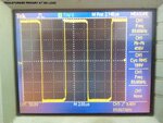
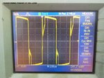
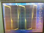
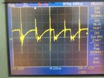
i have built a half bridge smps with pfc front end for 2 X 200W class - D . it works fine but the wave forms that i see is troubling me .... Can any one have a look and tell me if i am doing it wrong ..... the smps has a open voltage loop . wat is troubling me is primary waveform at 90% load the wave form should be flat during the dead time which it is not ....

View attachment Protel Schematic.pdf

regards
phoenix
 

Attachments

  • TRANSFORMER PRIMARY AT NO LOAD.JPG
    TRANSFORMER PRIMARY AT NO LOAD.JPG
    304.1 KB · Views: 153
  • TRANSFORMER PRIMARY AT 50% LOAD.JPG
    TRANSFORMER PRIMARY AT 50% LOAD.JPG
    355.9 KB · Views: 144
  • TRANSFORMER PRIMARY AT 90% LOAD(1).JPG
    TRANSFORMER PRIMARY AT 90% LOAD(1).JPG
    334.3 KB · Views: 127
  • CURRENT WAVEFORM AT CT SECONDARY UNDER 50% LOAD.JPG
    CURRENT WAVEFORM AT CT SECONDARY UNDER 50% LOAD.JPG
    393.3 KB · Views: 151

Hi,

no need to worry.

without load (picture1) the waveform seems like a pure square wave. But it is driven: 41% high side / 9% OFF / 41% low side / 9% OFF. (estimated %)
One can not recognize the 2 x 9% OFF time.

During OFF there is stored energy in the core of the transformer. This causes the voltage to go to the opposite side of the last driven polarity.
Since there is no load (current) there is no power and there is enough energy to keep voltage level high (negative or positive; far away from zero)

On picture2 and 3 there is load. And the waveform during dead time (fast rising to the opposite voltage, then fast step back and then medium fast rising) is a combination of the transformer´s stored energy and the inductances CMNF1 and CT:1.
The slowly falling top is caused by the increasing current and the decreasing voltage of the input capacitors.

How did you measure picture4? With a current probe?

Klaus
 

dear klaus
i had placed a current transformer in series with txfrs primary ....
how do i know if my core is not saturating ....

regards
 

Hi,

how do i know if my core is not saturating ....

I can´t find a saturation here. (As long as picutre4 shows the current of the primary side of the transformer)
Saturation would cause an immediate current rise at the end of a cycle.
Saturation: a more vertical line at the end of cycle, but here i see a relaxed horizontal end of cycle.

Klaus
 

but my transformer heats up very fast .... the etd39 reaches 90C after 15mins ..... at a load of 500W ... find attached the transformer design page....

regards
 

Attachments

  • IMG_20141024_102857.jpg
    IMG_20141024_102857.jpg
    3.4 MB · Views: 115

but my transformer heats up very fast .... the etd39 reaches 90C after 15mins ..... at a load of 500W ... find attached the transformer design page....

regards

  • -your transformer specs will tell you the problem for max current AC and for winding losses and eddy current losses.
  • Note core losses are for sinusoidal and derate B with rising f .
  • what core grade?
  • What winding details for resistance,,N turns what B do you calculate.
  • what is clamp force?
  • Gapped core is more consistent.


-ferrite inductance also degrades with copper losses as they get hot leading to potential thermal runaway.


Also your MOSFETs are 230mOhm at 25V and this doubles at 110'C for Tj.
 

Primary inductance - 5.82mh
Primary DCR - 110.95mE
Primary leakage - 17.5uh(did the measurement while shorting the secondary)
secondary inductance - 449uh
secondary DCR - 17mE
Secondary leakage - 3uh(did the measurement while shorting the primary)

Transformer winding details -
primary - 21 + 21(split design for better coupling)
secondary - 13 + 13
I have used a Bmax - 900gauss or 0.09T
 

90mT and frequency content> 100kHz is your problem. this device even at premium 3F3 grade is on rated at 50mT at 400kHz with 2.5W dissipation and 100mT at 100kHz.

Your square wave at 90mT at 90kHz contains harmonics at 1/3rd the fundamental level at 270kHz and 1/5th at 450kHz. The combination of this spectral density appears to be causing excessive eddy current losses in the core.

Look,for a bigger core with lower permeability than 1600 to get same inductance. Lower RdsOn and wire resistance total will improve droop at then same peak current.

Reducing the clock rate may increase current so lower duty cycle is needed, which only increases harmonic content.

  • -the other possibility is consult with vendor on gapped cores.
  • Remember the energy is stored in the gap,
  • In gapless cores it is stored in the gaps between magnetic particles.
 

is there by any chance .... cross conduction happening as i am driving the higher side mosfet with a transformer and the lower side with a totem ...
and do i need gapped core for half bridge ????
 

Your notes say 48 turn primary buy your post says 42 turns. How many turns did you actually use.
 

Status
Not open for further replies.

Part and Inventory Search

Welcome to EDABoard.com

Sponsor

Back
Top