dilzam
Newbie level 2
I have two Servodyn-D servo motors [SF(R)–A4.0230.060]. When connecting power to the encoder(ECN1313), do we have to supply +5V from an external power source? Or the motor has its own +5V power supply to provide the power to the encoder ?. I believe that we need to input power to +5V and 0V pins. We don't have to power 5V(sensor) right? Could you please correct me if I am wrong.
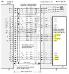
What are the R+ and R- Reference signals in following encoder pin out diagram? ( There are two pins called- timing). I have attached the diagram here(Figure1-Encoder Pinout).>>>
And what does two "data" pins and two "timing" pins exactly do?. My intention is to connect the 17 pin Bosch encoder cable to 12 pin connector of the Heidenhain IBV 610 unit. I have attached the diagram here(Figure2 (Pin Diagram))>>>
The needed datasheets(Motor datasheet and Heidenhain Interpolation and digitizing units) also attached herewith.
Thank you.
What are the R+ and R- Reference signals in following encoder pin out diagram? ( There are two pins called- timing). I have attached the diagram here(Figure1-Encoder Pinout).>>>

And what does two "data" pins and two "timing" pins exactly do?. My intention is to connect the 17 pin Bosch encoder cable to 12 pin connector of the Heidenhain IBV 610 unit. I have attached the diagram here(Figure2 (Pin Diagram))>>>

The needed datasheets(Motor datasheet and Heidenhain Interpolation and digitizing units) also attached herewith.
Thank you.