Continue to Site

Welcome to EDAboard.com

Welcome to our site! EDAboard.com is an international Electronics Discussion Forum focused on EDA software, circuits, schematics, books, theory, papers, asic, pld, 8051, DSP, Network, RF, Analog Design, PCB, Service Manuals... and a whole lot more! To participate you need to register. Registration is free. Click here to register now.

Need help making or finding really simple circuit - huge noob

Status
Not open for further replies.

shibe

Newbie level 6
Joined
Oct 19, 2014
Messages
12
Helped
0
Reputation
0
Reaction score
0
Trophy points
1
Activity points
99
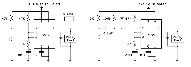
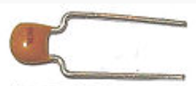
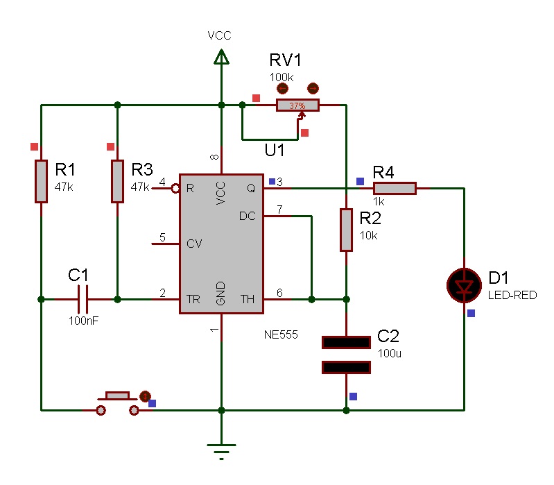
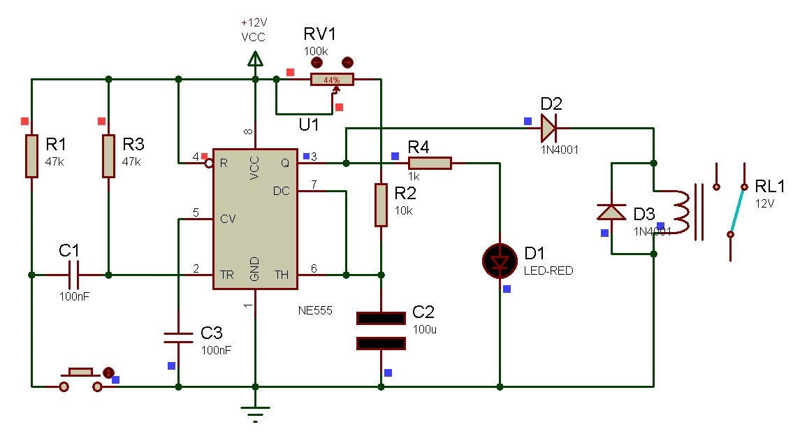
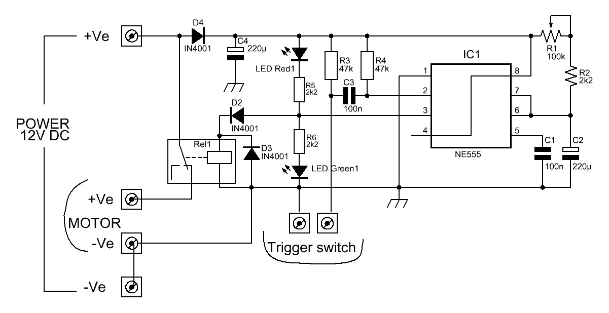
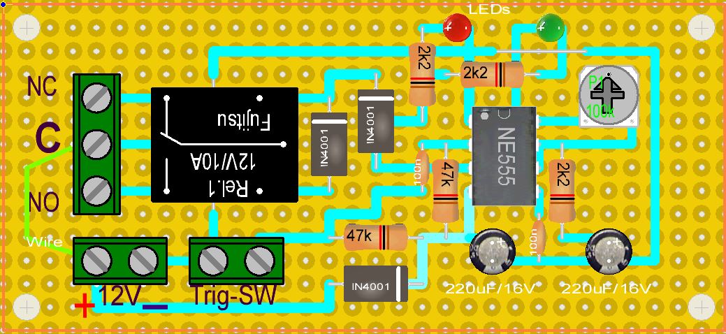
I need a relay circuit with an output of 12v. I need the relay to be activated by a button and run for a duration of time that is set with a knob/trimmer. times only need to be adjustable from 1-20 seconds roughly. when the timed circuit ends, it does not start again until the button is pushed. It would be nice to have a red led when off and a green led when running for duration.

I know this will probably be simple and I am willing to bet that there is a pre-built option for this somewhere online, but i do not know what I would be looking for.

So if anyone one is willing to point me in the right direction or help me build this, I would be very appreciative!
 

555_relay_sch.jpg


Here is what you require.
http://cdselectronics.com/kits/timer relay.htm
 

ALERLINKS has been helpful thank you. I need help building this still so anyone on the forum please let me know if you want to help me build this or do it for me for donation. Here are the PMs with ALERLINKS.

shibe said:
Thank you for your replies, you are very knowledgeable!! I know so little I barely understand your schematic! If I gave you an extended idea of what i need would you be able to make a schematic for that? Its basically what you've already shown me but with multiple 12v motors.

What I will have is six 12v motors, all controlled by 6 individual "push" buttons. Each Motor will need a trimmer to set the run time. A 7th button would be convenient but not necessary, this button would run/trigger 3 of the motors for their set duration, either simultaneously or sequentially.

I know this is a simple circuit and I could probably learn how to do it all, but would you be willing to build this for me and send it to me? I would pay you for all the parts and your time, via how ever you like.

If youre not comfortable with that.. If you were to put together a parts list and a small tutorial I can tip you for your time by sending you bitcoin or dogecoin if you participate in cryptocurrency.

Thanks again ALERTLINKS!
shibe said:
ALERTLINKS said:
I and many others can assist you to make it work. Ask it in the thread. What is the current ratings of the motors? You can avoid relays and use FETs to make it more simple and compact. It will be easy if you can get components from near you. Although I can make and send it to you but you can try, it will not be difficult.

Motor voltage: 12VDC
Motor current: 200-300mA

could you make me a schematic for this? Im going to try and make it myself! I have never done this and looks fun. I will also ask in the forum. OR I will post your schematic and details after. I am also unfamiliar with reading schematics and what parts are what. I am good at soldering but am not confident in electronic parts and the order in wich theyre soldered.
thanks!!
 

Get aquanted with some basic components and their symbols
pushbutton switch, normally open
536.s.png

Push switch (Single pole, single throw)
6731934200_1414506151.jpg

8820219700_1414505828.jpg


Resistor

https://en.wikipedia.org/wiki/Resistor
120px-Resistor%2C_Rheostat_%28variable_resistor%29%2C_and_Potentiometer_symbols.svg.png

"a"
200px-Resistor.jpg


"b,c"
Variable resistor
https://en.wikipedia.org/wiki/Potentiometer

220px-PCB_variable_resistors.jpg


It is difficult to print and read numbers resistors, so its value is encoded with color rings.
Color code

resistor-color-chart.jpg


Capacitor
https://en.wikipedia.org/wiki/Capacitor
120px-Capacitor_Symbol.svg.png

5640677600_1414504875.png


Capacitor, polarized
120px-Polarized_capacitor_symbol.svg.png


220px-Condensador_electrolitico_150_microF_400V.jpg


Electronic symbols
https://en.wikipedia.org/wiki/Electronic_symbol

LM555 IC
https://en.wikipedia.org/wiki/555_timer_IC
220px-555_Bistable.svg.png


"Top view"
220px-555_Pinout.svg.png

220px-Signetics_NE555N.JPG


LED
https://en.wikipedia.org/wiki/Light-emitting_diode
7762001900_1414506510.jpg


220px-LED%2C_5mm%2C_green_%28en%29.svg.png


I shall post further detail meanwhile try to figure out from schematic. It will require six similar circuits.

A circuit and its simulation driving an LED,
2916153900_1414511882.jpg
 

Attachments

  • 555 timer.rar
    276.7 KB · Views: 61

Now with relay and motor.
 

Attachments

  • 555 timer-relay.rar
    484 KB · Views: 67

Wow thank you! I think I actually understand that schematic for the most part now! So If I were to make six of these boards, how would I wire them to a single power supply, and also what size/type of power supply would I need?

Also what kind of attachment circuit could I make that would run 3 of the motor circuits sequentially (not at the same time, because I think the power draw would be too much and slow down the motors, correct me if I'm wrong)?

Some of the parts on the schematic I am still unsure what they are exactly or how to find them. If you label all the parts for me on the schematic with their full names then I should be able to order the parts and get it all soldered together. I don't want to miss order anything, so could you make a full parts list? Thanks again!
 
Last edited:

Why does that schematic have a push button and a push switch? Also, is it the variable resistor that determines run duration?

- - - Updated - - -

Ok just one more thing alertlinks, if you give me a list of the part names on that schematic I think I could order them all and do the soldering. The schematic has details but I don't want to miss order anything, so labeling each part with its full name would make this a possible build for me! Thanks again!
 

Ok, I think I have my parts list sorted with everything I need. But I am confused on two segments of the schematic on what parts to use. here is a picture of what I need to clear up before I move on and can build this thing.

2630275200_1414566348.png


If you can explain those to me then I think Ive got it!
 
Last edited by a moderator:

I did not described about these two components.
Diode
images

images

IN4001
https://en.wikipedia.org/wiki/Diode

Relay
It consist of a coil and a switch. When current passes through coil, it makes a magnet which pull the switch to close. This internal switch then controls the motor. You can observe this action in animation video.
https://en.wikipedia.org/wiki/Relay
300px-Relay_symbols.svg.png

Relay2.jpg


2630275200_1414566348.png

This is variable resistor. It controls on_time. Its value is 100k. If you need to turn it often, then use bigger one such as used for volume control with a knob. If you only want to set time for once, then use small preset. As schematic was captured during animation and it was turned near halfway, that's why it is showing 44%, indicating its setting. Watch this action in the video when its value is changed and on_time is varied.


I will make parts list and layout plan.
 

Thank you! a couple more questions..
I think I have found the right spdt relay, it has five pins. Which pins connect where? The motors +/- connect to the spdt relay, correct? and which relay pins connect to the diode?
Also, what size and type of power supply should I use to not damage the fet?
 

FET is a solid state switch which can be used in place of relay but we are using relay which has a mechanical part. In most cases coil does not have a polarity until it has a built-in diode. If you have a multi-meter you can check resistance of coil on some two points. Normally it is shown on relay.
8904794300_1414588774.jpg

You can make relay board separate from other circuit with connectors.
7750199000_1414588910.jpg

7541939500_1414588993.jpg


Get a power supply which can provide enough current to run the motors simultaneously which are ever active. For example if three 12V motors are on, and each draws 300mA then add all. It becomes 900mA. Initial current is higher so give it a margin. Make it double. A 12V/2A will do. It does not matter if it can supply more current.
Higher, the better.
 

I have used those blue relays with raspberry pi projects so I understand that relay and I understand the power supply needs, thank you so much.
The ports im familiar with on the blue relay are vcc, ground and the trigger wire, which of these ports conects to the diode and the +/-? If i am using a 12v psu for the motors/relays, what psu do I connect to the 555 +/-? Can I power the 555 and relay vcc from one power source?
 

If you show picture of the relay you already have, we can make it work. The blue relay board, you are describing may already diode and relay driving transistor. That's why their is trigger input instead of connections for coil. As motor and circuit require 12V. A single supply can drive both.

Now timing component adjusted to set interval from 0.5Sec-24Sec. Added red Led for off indication and connections to use single supply.
 

Layout:


Parts List for one board

Resistors: (All 1/4 watts 5%)
2.2KOhm 3no
47KOhm 2no
Variable resistor, 100KOhm 1no
Capacitors:
100nF 3no
220uF 2no
Diodes:
IN4001 3no
LED red 1no
LED green 1no
IC:
NE555
Misc:
12V relay
Vero board
connectors
 

Here is the relay board I have: https://www.amazon.com/gp/product/B0057OC5WK/ref=oh_aui_detailpage_o06_s00?ie=UTF8&psc=1
Your last two layouts appear to be different, which one should I use? The variable resistors that I have seen have 3 pins and the layout shows 2?
I almost understand enough to start buying parts for this project, i am unsure about the trigger/switch and variable resistor placement. Could you look at the link and tell me if those relays will work for this layout? thanks!
 

images

This is this type. It has three terminals. Centurial terminal is connected with either side.
you can use any type, only connect two adjacent leads on either side.
6833277200_1414749673.jpg

5769440800_1414749673.jpg

7922852900_1414749674.jpg

Switch is separated from layout so as to easily place it on some convenient place for example on dial or you can put it directly on pcb in place of trig_connector.
What else you see the difference. This layout is for last schematic in post#14.
The board, you have, has following specifications.
Power Supply: 5V DC / 400mA (relay all ON)
Input control signal voltage:
0V - 0.5V Low stage (relay is ON)
2.5V -5V High state (relay is OFF).
Input control signal LOW state current:
2.5V: 0.1mA.
3.3V: 0.18mA.
5V: 0.35mA.
JD-VCC or VCC: Power supply input, 5V DC. (JD-VCC RELAY POWER VCC:SYSTEM VCC)
GND: Power supply ground and control signal ground.
CH_x: Control signal input, Low: relay ON, High: relay OFF.
COM / NO / NC: (C1=COM1, C2=COM2)
Control signal state low, the relay ON, COM - NO disconnected, COM - NC connected.
Control signal stage high, the relay OFF, COM - NO connected, COM - NC disconnected
Basic difference is that, it operates with 5V and its input is inverted that means when input is high, relay is in off state and when input is zero, relay will turn on. It can work with our circuit after slight modifications or if you can programme a microcontroller, the whole circuit functions can be generated with a microcontroller for example a PIC16F877. I can make a hex code for this application.
 

A video is attached. There are six independent timers using PIC microcontroller.
 

Attachments

  • 6timers.rar
    44.3 KB · Views: 55

If you think it would be easier to use a rasp pi, relay board and hex code then lets do it that way! Would I just have a monitor and mouse connected to my rasp pi and it will work like in the video? That would be perfect!
 

I don't have experience with rasp pi. It has recently became available in market. The video is simulation of hex file using PIC microcontroller. It require less components to assemble.
 

Status
Not open for further replies.

Similar threads

Part and Inventory Search

Welcome to EDABoard.com

Sponsor

Back
Top