Continue to Site

Welcome to EDAboard.com

Welcome to our site! EDAboard.com is an international Electronics Discussion Forum focused on EDA software, circuits, schematics, books, theory, papers, asic, pld, 8051, DSP, Network, RF, Analog Design, PCB, Service Manuals... and a whole lot more! To participate you need to register. Registration is free. Click here to register now.

[SOLVED] CE amplify positive half signals more than negative one !!!

Status
Not open for further replies.

MahmoudHassan

Full Member level 6
Joined
Oct 4, 2010
Messages
349
Helped
44
Reputation
90
Reaction score
40
Trophy points
1,328
Activity points
3,913
Hello
Dear All,
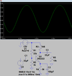
i tried to design a simple CE amplifier but i found that it amplifies the positive half cycles more than negative ones !!!What possible faults that may cause this error ?

The gain is supposed to be 20 (but it is 24 after design acceptable)
Rin > 2Kohm
Beta for this transistor ~= 255
Is = 14.34 *10^-15 A
Freq = 20 Hz -- 20 Khz

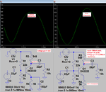
Attached figures for the design and output signals using parametervaring the input voltage ,when is the input voltage is larger than 0.5mV the the amplifier starts to amplify the positive half cycle more than the negative one
i hope you can give me reasons for this fault so that i can improve this design
(This is not HW , iam studying Fundamentals of microelectronics self study and trying to design example in chapter 5 )

Thanks a lot
Best Regards,
Mahmoud

rr.JPGrr2.JPG
 

That's no fault, it's the expectable result of nonlinear transistor characteristic. If you like, you can quantify nonlinearity as T.H.D. (total harmonic ddistortion) by performing a fourier analysis.

To reduce distortion with large signal magnitude, you can add negative feedback to the amplifier circuit. Most easily, disconnect C1 and increase the input level until you see a similar output magnitude. Distortion will be considerably lower then. Or add a smaller feedback amount by placing a resistor in series with C1, e.g. 50 or 100 ohm.
 
Thanks a lot for your help ,really helped a lot
but i have question , i thought that RE is enough for the negative feedback required to stabilize the biasing point, why should i need another resistor in series with C1 , if i already done that with RE , is it type of compensation like Opamp ????
 

Thanks a lot for your help ,really helped a lot
but i have question , i thought that RE is enough for the negative feedback required to stabilize the biasing point, why should i need another resistor in series with C1 , if i already done that with RE , is it type of compensation like Opamp ????
RE provides negative feedback for the bias point but not for the AC signal, since RE is bypassed by C1.

To provide emitter AC feedback add a 20 ohm resistor (connected to emitter) in series with the 200 ohm resistor and connect C1 between the two resistors to ground. To get the desired gain you may have to reduce the value of R4 (say to 100k) to increase the collector bias current (which increases the transistor Gm).

Some of that difference in amplification may be an artifact of the simulation. Run the simulation for about 50ms before taking the data to allow the various coupling capacitors to settle down.
 
Last edited:
Your emitter capacitor C1 shorts the emitter resistor which kills all AC negative feedback.

Why is the DC collector voltage so high that the transistor is almost cutoff?
I simulated it and got a voltage gain of only 30.1 times.

I corrected the bias so that the DC collector voltage is 6.3V and got a voltage gain of 181.3 times. Without any negative feedback at higher levels it is EXTREMELY distorted even when it is no where near clipping.

i didn't get it totally , cut off happen when VE larger than VB and this not happened in this case i think because VE is around 400mV

can you share simulation files with me ?
Thanks a lot
your time is really appreciated
 

Your emitter resistor value is much too high. Use about 1/10th the collector resistor, maybe 56 ohms.
Your transistor is almost cutoff because its collector voltage is very close to the 12V supply. The collector voltage should be about 6.5V and has 5.5V across it so the collector to emitter current is 10mA. The collector can swing up to 12V and down to about 1V.

Your voltage divider resistors that supply base current have values much too high.
Your 4000uF capacitor value is much too high.
Do it like this:
 

Attachments

  • transistor.png
    transistor.png
    20.7 KB · Views: 144
I want to show you what happens when the output level is fairly high with no negative feedback: Severe Distortion where the top of the waveform is not clipping but it is squashed.

When C2 is removed then there is plenty of negative feedback which reduces the voltage gain and it also reduces the distortion.
 

Attachments

  • transistor again.png
    transistor again.png
    41 KB · Views: 150
Due to the radical drop on Ic and hFE as Vc approaches V+, my simple design rule of thumb is keep out of the zone 2V below V+.
I tried that then the distortion "dropped" from about 40% to about 30% which is still horrible.
Without any negative feedback the distortion is fairly low only when the output signal level is tiny and is near ground.
 
Thanks a lot really appreciated your efforts and guiding
i don't know how to express my thankful for all of you guiding me to learn better
Iam really grateful to all of you :)

- - - Updated - - -

I want to show you what happens when the output level is fairly high with no negative feedback: Severe Distortion where the top of the waveform is not clipping but it is squashed.

When C2 is removed then there is plenty of negative feedback which reduces the voltage gain and it also reduces the distortion.

Can you tell me what is the program you are using for simulation ???
 

Can you tell me what is the program you are using for simulation ???
Most of us here and I use the free simulation program called LTspiceIV which is available as a free download from the website of IC manufacturer Linear Technology.
 
Iam very thankful for you
god bless your efforts :)
 

Status
Not open for further replies.

Part and Inventory Search

Welcome to EDABoard.com

Sponsor

Back
Top