Continue to Site

Welcome to EDAboard.com

Welcome to our site! EDAboard.com is an international Electronics Discussion Forum focused on EDA software, circuits, schematics, books, theory, papers, asic, pld, 8051, DSP, Network, RF, Analog Design, PCB, Service Manuals... and a whole lot more! To participate you need to register. Registration is free. Click here to register now.

4.5DC Motor controller help

Status
Not open for further replies.

graygem

Member level 1
Joined
Sep 21, 2010
Messages
33
Helped
0
Reputation
0
Reaction score
0
Trophy points
1,286
Activity points
1,508
I need a motor controller for a 4.5dc motor. Can this one from Talking Electronics "200 Transistor Circuits" be used or what would I need to do to make it work? I would also like to use SOT-23 transistors, would that be ok?
Thank you in advance.
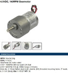
Motor Speed Controller.jpg
 

This might work. But as far us using SOT-23s, that all depends on the motor current; 4.5V doesn't tell us anything. How many AMPS does it draw?
 

I was looking at this one.
 

Attachments

  • Motor Speed Controller MPJ Motor.jpg
    Motor Speed Controller MPJ Motor.jpg
    160.4 KB · Views: 125

The circuit with normal size transistors is designed for motors that have a stalled current of from 50mA to 100mA. Your motor current is up to 64 times higher.
One or two transistors must be power darlingtons and many parts values must be changed.
 

Ok, maybe something totally different. Any suggestions? I'm trying to keep parts count to a minimum. I plan on powering it with a 12V supply.
 

Ok, maybe something totally different. Any suggestions? I'm trying to keep parts count to a minimum. I plan on powering it with a 12V supply.

Chosing a 12V supply only adds excessive wasted power ( 30W on startup ) and extra parts to limit current to 3.2A stall current @ 4.5V

Better choose 5V supply with 15A Schottky diode drop or a 4.5V regulated supply

Driver should drop < 100mV @3.2A start current = 320mW @ RdsOn= 0.1V/3.2A= 33 mOhm with 5V logic level drive.

Do you want fast stop too? then you need a half bridge with low RdsOn per above.

Best bet for SMD N MOSFET
https://www.digikey.ca/product-detail/en/AO3416/785-1011-1-ND/1855953
 

I guess life just can't be simple :lol: Yes, I need to stop fast as well.
 

Then you need a half bridge to push pull the rails with <=33 mOhm for low dissipation with Vgs threshoLd of 2.5 each so that at midpoint both MOSFETs are off with a common gate. The P type uses negative 2.5V Vgs so source is on 4.5V and N type uses source to 0V

If supply increase near 5V the FETs shoot through and short out supply.

If you dont understand, buy a 4A motor half bridge for $10 vs design your own for $2 not counting assembly parts. But check Vdrop in MOSFET bridge when you choose supply which , if 12V must use PWM control at ~35% max. And require heatsinks.
 

Thank you. Can you give me an example of what I should buy? Ebay maybe?
 

Something like this from talking electronics? I'd have to change the NPN MOSFET and add a PNP MOSFET. I'd also have to change the zener. What MOSFETs should I use? It would be cheaper to purchase one, if I knew where to get one from.

12V Cordless Drill Motor Controller.jpg

To this?

4.5V Motor Speed Controller.jpg
 

The power stage configuration makes no sense. You'll either use a switch with freewheeling diode as in the original circuit or a synchronous pus-pull switch. Your circuit is neither of it.

The PWM generator doesn't work well with LS14 IC due to it's high input current. Stay with CMOS.
 

Please edit my pic so I can see what you mean, adding suggested parts. This is all new to me. I'm learning as I go.
 

The original, You said would not work without a lot of parts change using the 4.5Vdc motor with a 3.2A stall. SunnySkyGuy said to use a H-Bridge. So I tried finding something like that. The second if for a 12Vdc H-bridge. I am self learning this stuff. Show me the right way, please.
 

A H-bridge would be used if electronic reversal is intended. The original circuit can work for 4.5 V although a half-bridge gives higher efficience. But why not start with the basic solution?


Ok, so I'm confusing myself. :) The original (post #1) wouldn't work for 4.5Vdc 3.2A Stall, so was scrapped. The second (post #10) would work with just changing to a MOSFET with a Vgs of 2.5?

12V Cordless Drill Motor Controller.jpg
 

Thank you. Can you give me an example of what I should buy? Ebay maybe?
Ebay never gives specs, I posted example PN already. Choose from site filter parameters, cost and stock on hand, then choose supplier

keyword .. Logic level driver
Yes correct you just need better single MOSFET.

if you prefer instant stop drill, then dual Mosfet or half bridge is required.

Then you need ... to push or pull the rails with <=33 mOhm for low dissipation with Vgs threshoLd of <=2.5 each
 

Ok, got it, but how would I do the "dual MOSFET or half bridge" for instant stop?
 

Status
Not open for further replies.

Similar threads

Part and Inventory Search

Welcome to EDABoard.com

Sponsor

Back
Top