Continue to Site

Welcome to EDAboard.com

Welcome to our site! EDAboard.com is an international Electronics Discussion Forum focused on EDA software, circuits, schematics, books, theory, papers, asic, pld, 8051, DSP, Network, RF, Analog Design, PCB, Service Manuals... and a whole lot more! To participate you need to register. Registration is free. Click here to register now.

Problem with LM741 output (help)

Status
Not open for further replies.

kookooli

Junior Member level 3
Joined
Jul 10, 2014
Messages
30
Helped
0
Reputation
0
Reaction score
0
Trophy points
6
Activity points
235
Hi,
i am using LM741 as an amplifier.
when my input signal is DC it works correctly, but when my input is AC it show more than what it should show
for example when my input is 0.9 dc with 6.6 gain it show 5.95 and that is correct but when my input is ac whith 0.9 rms with 6.6 gain , it should show 5.95 rms but it show 7.3 rms ?
why ??
 

.9V RMS =~2.5V p-p input, gain is 6.6, so output should be 16.5 V p-p. So you need at least+- 9V supply lines and the quiescent output should near to 0V. If the waveform is limiting its true RMS value increases, so I guess your "sinewave" is limiting.
Frank
 
thanks for your answer but i dont know why you say my sinewave is limiting ??
0.9 RMS means =~ 1.3 volt amplitude , so when my gain is 6.6 so my output amplitude should be =~8.6 volt , while my supply voltage is +-12 volt ,
if the output was more than 12 volt , you were right and the signal would be limited but in this case my supply voltage is more than my output signal , but i dont know why it doesnt work correctly ?
what do you think ?

what do you mean by " How do you measure Vrms ? " ?? :shock:
Have you heard any thing about " VOLTMETER " ??

Kind Regards,
Amin
 
Last edited by a moderator:

0.9V RMS is 1.273V peak or 2.55V peak-to-peak only if it is a pure sinewave with very low distortion. A sinewave that has limiting has its top and bottom clipped which is distorted.

A simple voltmeter measures a distorted waveform wrong. A deluxe voltmeter has an IC that measures odd and distorted waveforms with "true RMS".

Many voltmeters only measure 50Hz and 60Hz accurately. They show wrong numbers for higher frequencies.

The 741 opamp is very old and depending on the gain has very poor high frequency response.
 

With the supplements in your second post (+/-12 V power supply, sinewave input, multimeter used for measurement), you're slowly approaching a meaningful question.

We still have to ask about signal frequency and the actual amplifier circuit. Besides possible multimeter error, there are many reasons why an amplifier circuit might show frequency dependant gain.
 

Why don't you post a detailed schematic of your opamp amplifier including its load impedance or resistance? Show all resistor and capacitor values.
 

thanks for your answers but my circuit is more simple than what you think ...
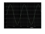
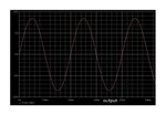
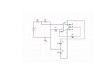
**broken link removed****broken link removed****broken link removed**
the first one is my circuit
second one is my input
and the third one is my output
these are my simulations in Orcad and in practice I use a 220/12 volt transformer and then i make 0.9 volt with resistors,
but in practice my RMS would be 7.3 that means 10.32 volt amplitude and I dont know why ?

and i know 741 is an old op-amp, but which op-amp do you suggest ?
Is TL071 a better one ?
 

Firstly the guaranteed LM741 output current is 10 mA, so the circuit don't necessarily work with the present resistor values for the intended output level. All datasheet specifications are for RL > 2 k. This doesn't explain why you're apparently measurinmg a too high output voltage, but should be considered though.

TL071 is clearly better than LM741 and a good general purpose OP for circuits like this.

A possible reason for inplausible measurements could be that your multimeter has a too large input capacitance and causes self oscillations of the amplifier when connected to the output. A series resistor (e.g. some 100 ohms) can be connected to the amplifier output to isolate load capacitances.
 
Your attachments are not jpg. Pls revise.

Gain BW product is constant so gain is function of freq, feedback gain and GBW product of Op Amp and as well, circuit load & slew rate.
 

yes, picture formats were .jpeg . I changed them to .jpg .
1.jpg2 (2).jpg3 (2).jpg
 

The input is about 1.3V peak and the output is about 8.6V peak. The peak output current is 8.6V/560 ohms= 15.4mA which is too high for most opamps. Your opamp must be stronger than most because the output does not look too distorted. The frequency is very low at 50Hz.

The gain is 8.6V/1.3V= 6.62 times. The gain should be 1 + (560/100)= 6.60 times. The small difference in gain might be the tolerance of the resistors.
 
Output current is 8.6Vp/(560+100)=12.8mAp. Your OPA is limiting. Increase R1 and R2 for 10 times and if it does not help increase supply voltage to +-15V but the easiest way to solve the problem is to decrease input voltage to 0.5V.
 
There is no problem. The 'scope correctly shows an AC gain of 6.6 times. If he measured it with a meter then the meter is wrong.
 

There is no problem. The 'scope correctly shows an AC gain of 6.6 times. If he measured it with a meter then the meter is wrong.
The description may me correct. But kookooli is apparently comparing a PSpice simulation (which shows the correct gain of 6.6) with a real hardware measurement under in detail unknown conditions. So for the time being we can't say more than that the real hardware would show the same result if it exactly corresponds to the simulated conditions. Who knows if it does?
 
The simulated oscilloscope correctly shows a little clipping distortion at the peaks of the waveform. So the simulation software knows that the very low values of the 560 and 100 ohm resistors are overloading the 741 opamp.
 
I think it is reasonable to increase R1 and R2 ,
and i think i have no choice except using an oscope for my practical circuit.
i would test my circuit and i will show you my waveforms.
and thank you very much for your useful opinions.
 

National spice model for LM741 has output voltage limit dependant on output current. At 660 ohm load it is 10.4V and at 6600 ohm it is 10.9V. Four other types of LM741 which I have has fixed limit at 10.9V. Supply is +-12V.
This comparison shows that models are inaccurate at extremes and simulation can be misleading.
Doubts can be resolved by oscilloscope.
 
Status
Not open for further replies.

Similar threads

Part and Inventory Search

Welcome to EDABoard.com

Sponsor

Back
Top