Continue to Site

Welcome to EDAboard.com

Welcome to our site! EDAboard.com is an international Electronics Discussion Forum focused on EDA software, circuits, schematics, books, theory, papers, asic, pld, 8051, DSP, Network, RF, Analog Design, PCB, Service Manuals... and a whole lot more! To participate you need to register. Registration is free. Click here to register now.

Chassis ground resistor any UL experts out there?

Status
Not open for further replies.

Jester

Full Member level 6
Joined
Aug 18, 2012
Messages
377
Helped
7
Reputation
14
Reaction score
7
Trophy points
1,298
Location
.
Activity points
4,754
I searched and read applicable previous posts regarding chassis ground.

I found this comments from Dickfreebird useful: "A metal chassis is a huge antenna and you may pick up an extra amount of electrical noise in your signal ground if you tie them hard. The chassis only needs to be at a man-safe potential and the rest of it you'd rather not "see".

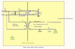
Circuit image to aid discussion:

1) So, it sounds like if you have a PCB in a metal chassis, best practice is to earth ground the metal enclosure (chassis), but not connect earth to the circuit on the PCB?
2) If the circuit board is in a non metallic (plastic) enclosure, is there any reason to introduce chassis ground to the circuit (either on the primary or secondary side?)
3) Seems common practice to connect the low voltage circuit ground to chassis (earth) either directly or via a R-C network, is there any reason to do this in a plastic enclosure?
a) I seem to recall the the creepage distance and possible HI-POT tests voltages are relaxed when the low voltage side is referenced to earth.
b) It seems like the low voltage circuit will/can float to any voltage if not referenced to earth.
 

Attachments

  • iso.jpg
    iso.jpg
    65.6 KB · Views: 215

Hi,

often the problem is WHERE the chassis is connected to the PCB and where the current flows.

The connection should be low impedance, so voltage difference between sensitive circuit and chassis is low.
Then the voltage is not that problem. but the current.

Just connect your chassis to the PCB and now try to imagine the path of the current.
Avoid that the current travels near sensitive circuitry.

Often a single point, where PCB gnd, earth gnd and chassis gnd is connected is a good solution.

In detail it depends on many parameters.


Klaus


There should be NO current flowing in the protective earth connection or between a chassis and a PCB within it.
I would suggest some light reading:
http://www.hottconsultants.com/
http://www.amazon.co.uk/Electromagnetic-Compatibility-Engineering-Henry-Ott/dp/0470189304
http://en.wikipedia.org/wiki/Extra-low_voltage
http://qtwork.tudelft.nl/~schouten/linkload/grounding.pdf

Searches on SELV, "double insulated" & "creepage and clearance" would also help.

NO current is pretty strong; there is often some leakage current, 1uA, 100uA, even 1mA?

I seem to recall the older 60950 standard defines acceptable touch current as < 3.5ma?
 

Hi,

There should be NO current flowing

of course there should no continous current flow.

But when you touch a chassis there will be ESD. Current.
If you are near a HF source (mobile phone) there will be HF current.


Klaus
 

RCDs trip at bout 30mA
Current and shock data 2nd page.
**broken link removed**
 

RCDs trip at bout 30mA
Current and shock data 2nd page.
**broken link removed**

Well 30ma may not kill you, but it will likely be very painful. My point about NO current is that there will often be some current to earth it's just usually limited to the extent it's not perceptible to the human touch (ie. less than 1 ma)

Back to the original question, with an isolated low voltage secondary circuit, when should the circuit be referenced to earth and when should it be allowed to float?
 

UL requires a list of all component specs connected to earth ground and Ac power. for grounded cordsets, the ground entry to case resistance must be <100mOhm, which is easily achieved with welded stud with spade lugs bolted via threads. the HIPOT test must be done 100% on AC,powered units with an option for 10% higher voltage in 1sec or DC @141% more. Thus any Line or Neutral to ground filter caps must be rated for Y1 class (self-healing).

UL is only responsible for safety and not EMC.

EMC is all about ingress ( Susceptibility) and egress (conducted & radiated emanations).

If ESD and radiated noise is a problem internal shielding and HV isolation is one solution, Faraday Cage (PC case) are another.

Generally if the unit is low impedance grounded for EMI and ESD reasons, one uses using 15 kV 50pF repetitive discharges to verify no damage. It should direct the discharge produce low E fields internally from case shield by diverting the path that current takes to earth ground.

If the unit is plastic, then the low common mode impedance is desireable on the internal power/Gnd while the plastic and creapage gap 1mm/kV in air, ~<0.1mm/kV in plastic is used protect arcs from intrusion.

( The original PC keyboards with LEDs failed miserably for this isolation and ESD would arc via the air gap around LEDs to leads.

If the unit is high impedance and any interface lines are not perfectly balanced, the high impedance electric fields get translated into a small differential voltage, enough to cause interference.

Two solutions used are Ferrite balun choke around cable ( llke all VGA cables) and also RC filter between AC and DC ground, such as 1kOhm, 100nF plastic.

( Laptop SMPS chargers are floating but are notorious for injecting hum in external high impedance Mics. Due to RF coupling across Transformer and lack of common mode rejection. An external ground to a VGA monitor usually fixes that. )
 

SunnySkyguy,

Thank you, lots of useful information in your post.

Are you describing an ESD test-->Generally if the unit is low impedance grounded for EMI and ESD reasons, one uses using 15 kV 50pF repetitive discharges to verify no damage. It should direct the discharge produce low E fields internally from case shield by diverting the path that current takes to earth ground.

Looking at the picture in the first post, imagine measuring mains voltage via T1 and A/D internal to a uController and then digitizing the data to be sent via RS232 port. Am I better off with or without R1?

Your advice is appreciated.
 

how to ground the chassis

UL reqthe ground entry to case resistance must be <100mOhm, which is easily achieved with welded stud with spade lugs bolted via threads. )

I am worried about my chassis earth ground connection. If I use screws, won't they come loose eventually?
A press fit or weld seems like the best idea, but is it economical for small runs? What fasteners would you recommend?
 

Loctite :)

Use locking washers & a strong hand.

Glad to hear it is so easy.

I have checked some old test equipment and that is how they seem to do it.

Are there any "official authorities" that recommend this method?
 

The lock washer method is in wide use. It is an easy and handy method to fasten a wire so it conducts to the chassis. The metal surfaces need to make good contact. The lock washer has several sharp points, which pierce the surface, creating multiple electrical contacts.

It is easier than soldering. It can be done with thick or thin sheet metal. With a little thought we realize this makes a weak point in the loop. I suppose it is the source of a frequent suggestion we hear about any electrical problem: "Maybe it's a bad ground."

In automobiles, the entire chassis is a ground connection. Personal experience...

My family had a car that developed a problem where the engine no longer cranked quickly. Headlights worked, everything else worked. Battery was charged, terminals clean, tightly attached.

Wanting to find the problem, I examined the battery ground wire. I found it terminated at a lug, attached to a bolt and lock washer. For years it had been exposed to water, grime, seasonal cycles. Rust had creeped between metal contacts.

I unscrewed the bolt. I sanded all surfaces which carried electricity. It brought the car back to normal.

At several points around a car, I have seen wires connected to ground screws, which go into sheet metal. It is quick and easy. It usually stays reliable for a few years.
 

The lock washer method is in wide use. It is an easy and handy method to fasten a wire so it conducts to the chassis. The metal surfaces need to make good contact. The lock washer has several sharp points, which pierce the surface, creating multiple electrical contacts.
. . .

I unscrewed the bolt. I sanded all surfaces which carried electricity. It brought the car back to normal.

At several points around a car, I have seen wires connected to ground screws, which go into sheet metal. It is quick and easy. It usually stays reliable for a few years.

In my decades old test equipment, the ground screw is still working fine. Autos face much worse conditions. But,
the auto voltages (12V) are not lethal, so a good ground is less critical. I would think if the metals were chosen properly and clean to start with, they would actually join chemically. (steel and aluminum will do that) , but maybe that is not wanted either.
 

Status
Not open for further replies.

Part and Inventory Search

Welcome to EDABoard.com

Sponsor

Back
Top