Continue to Site

Welcome to EDAboard.com

Welcome to our site! EDAboard.com is an international Electronics Discussion Forum focused on EDA software, circuits, schematics, books, theory, papers, asic, pld, 8051, DSP, Network, RF, Analog Design, PCB, Service Manuals... and a whole lot more! To participate you need to register. Registration is free. Click here to register now.

Dielectric resonator between two parallel microstrip lines. What current direction?

Status
Not open for further replies.

Terminator3

Advanced Member level 3
Joined
Feb 25, 2012
Messages
802
Helped
71
Reputation
142
Reaction score
63
Trophy points
1,308
Activity points
9,027
Hello!
Let's place dielectric resonator between two "infinite" microstrip lines.
On the one end of line we put RF source:
4833464600_1413341989.png

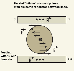
What would be current direction in second microstrip line?

Assuming coupling between lines goes only through DR...

original image from: https://mwrf.com/markets/planar-resonators-arm-tunable-oscillators
 

If your feed on the bottom line is from the left, the output signal on the other line will be to the right. The two other ends (top left and bottom right) are usually open circuit.
 
Here is the thing confusing me. In parallel feedback oscillators loop phase must be multiple of 360 degrees.
That means active device phase shift (s21) + microstrip lines phase shift + DR phase shift = n*360.
Here is two drawings:
parallel-feedback.png
If active device and DR are the same, would microstrip lines have same length in two cases?
If we look at my first post drawing and this is correct:
If your feed on the bottom line is from the left, the output signal on the other line will be to the right.
then

for left drawing:
1. comes from drain microstrip line to DR coupling point
2. goes through DR to gate microstrip coupling point
3. comes to gate microstrip line and goes up(!) until reflected by open stub, then goes down to FET's gate. So here it gets additional 180 deg phase shift? As open stubs are usually quarterwave (90deg) in parallel feedback DRO.

for right drawing:
1. comes from drain microstrip line to DR coupling point
2. goes through DR to gate microstrip coupling point
3. goes from gate microstrip coupling point to FET's gate
So here is no any additional 180 deg phase shift


Is it correct, that in this two cases (drawings on the left and right) microstrip lines would be not the same? It seems that on the left drawing we get additional 180 deg phase shift. But i am not sure about that, because quarterwave opencircuits acts as shortcircuit, and there may be something to deal with short circuit reflection.
 
  • Like
Reactions: ferdem

    ferdem

    Points: 2
    Helpful Answer Positive Rating
Why do we need to short circuit coupling points in parallel feedback DRO?

In the few papers i read that quarterwave line is added to the microstrip lines to achieve maximum current. In one paper from avago i found explanation to this as:
The length l1 should be 90 degrees at the frequency of oscillation. This will reflect a low impedance, hence a current maximum, at the point where the DR is coupled to the transmission line.
(you can find this in AVAGO's Application Note S005)
avago-dro-paper.png

from the dictionary:
"Reflected impedance" - a part of the impedance of an electric circuit that is due to the influence of another coupled circuit

But what do we achieve if current maximum is near Dielectric Resonator?
 

But what do we achieve if current maximum is near Dielectric Resonator?
I moved the new post to your previous DR thread because they are closely related. In fact the answer to your question can be already found in the post #1 diagram and more detailed derived from the previously linked papers.

Just consider that the DR coupling is provided by the magnetic field component.
 
Consider that the high impedance DR is coupled to low impedance voltage source by impedance inversion of 1/4 wave to understand basics. This conversion from M to E field with high Q resonator is enhanced with the Q of the 1/4 wave resonator coupling.
 
I have an additional question. At high frequencies (20GHz, 30GHz) dielectric resonator size is very small. When designing parallel feedback DRO, there are always two microstrip lines coupled to resonator. To obtain required coupling we must use optimal coupling distance between lines and resonator. But because resonator is too small, distance between parallel feedback "arms" becomes too small, and we get unwanted coupling, that going through lines and not through resonator. How to solve this problem?
 

Yes, unwanted coupling and "unwanted" modes are a problem. A few weeks ago, I helped a friend with his design. We used 3D EM simulation to model the coupling lines, the puck on a standoff and all that enclosed in a cavity. Our goal was to study the optimum coupling and loaded Q factor, and we found quite a few unexpected influences (e.g. spurious modes very near the design frequency, suddenly appearing/disappearing after very small changes to the cover height).

What level of S21 across the resonator are you trying to achieve? Have you checked with coupled line models what the crosstalk is without the dielectric resonator?

About 20 years ago, we had built a 24GHz DRO without EM simulation. The simulation software only had a circuit simulation model for the dielectric resonator coupled to a single line, so it was a lot of experiment. Looking back, I think our coupling to the DRO was too much ... but we got it to work. The phase noise wasn't a real issue in that system.

- - - Updated - - -

Addition: Here is a picture of that old design at 24GHz. Substrate was 0.51mm RO4003. Looking back, I think we had many mistakes, but hopefully this gives an idea what the distances were.

 
I just tried to scale 10GHz design to hypothetical 20GHz and 30GHz layout using idea in this thread : https://www.edaboard.com/threads/315121/ . I am not sure how to scale coupling, so i just halved size between parallel feedback "arms" at 20GHz, and take 1/3 at 30GHz. At 20GHz distance between arms becomes comparable to some microstrip band pass filter gaps. At 30GHz distance becomes too small, the same as filter coupling gap. Also there another problem: too thick too short lines for some substrates at high frequencies. So realistic layout requires adding multiples of 360deg length to feedback lines. Maybe because of that 24GHz DRO modules often use series feedback, for example http://www.ltcc.de/en/examples_act.php :
dro.jpg.
Some time ago i hoped to extract high frequency resonator puck from 24GHZ door opener sensor, and learn something from it's design. Unfortunately all of such sensors use microstrip resonator parallel feedback, and none of them used DRO. I've only seen dielectric resonators in 10GHz door openers and LNAs.

Thanks for the picture of your design.
 
  • Like
Reactions: ferdem

    ferdem

    Points: 2
    Helpful Answer Positive Rating
Also there another problem: too thick too short lines for some substrates at high frequencies.

You have some influence: you can use a substrate with lower erel to increase the physical length, and you can use a thinner substrate to reduce the width.

So realistic layout requires adding multiples of 360deg length to feedback lines.

Sure, but why not?
 
I have realized that one of my previous simulations addresses the question exactly. According to the simulation, induced current in the second trace flows into both ports.
 

Does it mean we have two directions of propagation with same phase in second microstrip line?
 

https://www.youtube.com/watch?v=38-zjbDQTak
I hope somebody see the video ferdem posted and give more comments. From what i see magnetic field in second line induced two directions of propagation. It is easy to observe 180 deg phase shift in upper part, as direction in both lines is identical.

And for this question:
https://www.edaboard.com/threads/324859/#post1389309
it seems that microstrip feedback lines would have identical lengths, as phase shift is 180 deg in both cases, and direction of propagation is correct for both cases.
Also it gives an idea that both feedback lines can have arbitrary length and terminated with 50 Ohm resistors, instead of making quarterwave open. It can help to align resonator when phase is unknown. Also i can imagine low-pass microstrip filter or some attenuators at the open end to achieve the same effect of arbitrary length feedback lines.
 

Status
Not open for further replies.

Part and Inventory Search

Welcome to EDABoard.com

Sponsor

Back
Top