Continue to Site

Welcome to EDAboard.com

Welcome to our site! EDAboard.com is an international Electronics Discussion Forum focused on EDA software, circuits, schematics, books, theory, papers, asic, pld, 8051, DSP, Network, RF, Analog Design, PCB, Service Manuals... and a whole lot more! To participate you need to register. Registration is free. Click here to register now.

[SOLVED] 140VAC out of the wall outlet

Status
Not open for further replies.
P

ParkerMike

Guest
When measuring AC outlets at different nightclubs, the AC outlets are higher at 140VAC.

Can Power Conditioners or a UPS system handle 140VAC outlets as the power source?

I would think it can cause the power transformers in a power conditioner or UPS system to open or short out?

I'm not sure how high in VAC a power transformers primary can handle from an AC wall outlet

If I use a Variac on a 140vac wall outlet , I can't bring the 140vac down because a Variac dial max is at 120vac , plus it will open or short out the variac transformer plugging it into a 140vac wall outlet i would think

Plus when I'm measuring with a DVM meter in AC mode, it's RMS at 140VAC

The 140VAC RMS is higher in voltage because it's RMS not at peak so the AC wall outlet is at 160VAC peak right?
 

If you are in United States or Canada the wall outlets are from 115V to 120V RMS.
Something is wrong when you measure 140V RMS. Maybe your meter is wrong because it has been overloaded

Why do you ask about 160V peak? It is 113.1V RMS. 120V RMS is 169.7V peak. A DVM does not measure peak voltages.
 

A DVM does not measure peak voltages.

Yes i know, what meter does? does a phase angle meter?

When I'm measuring an AC wall outlet and it's 140RMS , what is the peak voltage?

Yes the USA wall outlet is 120VAC at 60hz but for some reason it is output is 140VAC at 60hz

What is wrong with the wiring of the outlet? it should be at 120VAC but it's outputting 140VAC

How can I bring down the voltage from 140VAC to 120VAC?

Because if I hook up a Variac, power conditioner or UPS , it will damage the power line transformer because it's at 140VAC out of the AC outlet in the wall.

Maybe your meter is wrong because it has been overloaded

How can you overload a DVM meter?

If you are in United States or Canada the wall outlets are from 115V to 120V RMS.

Yes I know, but when i measure it , it's at 140vac at 60hz , there is something wrong with how they wired up the building or company

- - - Updated - - -

Also when nightclubs hook up stage lights that turn off and on and blink fast on and off it causes harmonics , noises, other things to be on the AC line on the outlets, why is that?

A washing machine that was running was reflecting back into the AC line outlet, causes oscillation sounds, harmonics, noises on the AC line outlets

Which you disconnect all the lights and fax machine, washing and dryer machines in the buildings , the AC line was cleaner

What can fix this problems and why does this happen?
 

If you connect a 110V light bulb to the outlet, if it is truly 140RMS then the light bulb will last for 10 seconds. You can connect a Variac across 140 V, it will draw a higher current but will work. If you set it for 50%, it will produce 50% of the input whether its 110V or 140V. As explained its the rubbish the disco light dimming systems are putting out on the mains. Try using a moving coil meter.
Frank
 

When I'm measuring an AC wall outlet and it's 140RMS , what is the peak voltage?
Please learn about the basic rules and formulas of electronics.

What is wrong with the wiring of the outlet? it should be at 120VAC but it's outputting 140VAC
How can wiring increase a voltage?? Did you try measuring the voltage with another meter?

How can you overload a DVM meter?
Feeding it too much voltage or too much current. Dropping it. Is it a cheap Chinese DVM? Did one of your "techs" fiddle around inside it?

Also when nightclubs hook up stage lights that turn off and on and blink fast on and off it causes harmonics , noises, other things to be on the AC line on the outlets, why is that?
Obviously each time a light turns on it draws current. An incandescent light bulb draws a very high surge of current for a moment until its filament reaches 2000 degrees C. Ohm's Law says the resistance of the wiring causes a voltage drop when it has current from the turned on light. Then the light turns off and the voltage returns to normal. The voltage going up and down a little causes noise and harmonics.

What can fix this problems and why does this happen?
You talked about a dirty AC line but did not say how you measured it and how much or how little voltage changes it caused. Why do you think it is a problem when it is probably normal so why "fix" it?
 

Beware that simple DMM only rectify , filter & measure peak voltage and scale to RMS by /√2.

If you are getting false readings check AC with DC. If you get 2x output rather than 0, it proves you are rectifying input.

If there are spikes on AC, you WILL get false high readings. A more suitable test method is required.

Better Phase Angle Meters will filter only the fundamental 50 or 60 for Total input.
 

How can I bring down the voltage from 140VAC to 120VAC?

Because if I hook up a Variac, power conditioner or UPS , it will damage the power line transformer because it's at 140VAC out of the AC outlet in the wall.

No. Variac input can handle full rated input voltage and Tap output slides from 0 to 120% typ.

How can you overload a DVM meter?

By ignoring rated max on meter front or reverse side. mandatory safety requirement. Typ. 250V min. Limit.

Yes I know, but when i measure it , it's at 140vac at 60hz , there is something wrong with how they wired up the building or company
Normal is 120Vac with 10% tolerance for distribution but more tolerance error can occur if site has adjustable dedicated transformer taps serviced by maintenance staff. Equipment may or may not be designed for 20% tolerance or may be universal 90-260. 50/60Hz

Also when nightclubs hook up stage lights that turn off and on and blink fast on and off it causes harmonics , noises, other things to be on the AC line on the outlets, why is that?
Impulse is defined by broad spectral noise, thus triacs and 10x surge currents from filament lamps causes large EMI spikes which can get into audio high impedance inbalanced cables. Thus 600 Ohm balanced is used on stage and mixer boards.

A washing machine that was running was reflecting back into the AC line outlet, causes oscillation sounds, harmonics, noises on the AC line outlets

Which you disconnect all the lights and fax machine, washing and dryer machines in the buildings , the AC line was cleaner

What can fix this problems and why does this happen?

These transient sources especially Triac controlled create a step load and depending on source impedance of transformer and line resistance, step currents will create broad noise transients.

The derivative of a step is an impulse like hearing lightning noise on any AM radio channel.

To fix, you either improve reduction of noise using a line filter unit at source or at dstination if feasible ( light pulser) for rated RMS current.

This uses magnetic PI filter and EMI caps that are designed not to saturate with rated current. it works by raising Common mode impedance then a differential filter cap can attenuate spectral noise. All PC PSU SMPS use these ro co,ply with IEC/FCC conducted noise emissions levels. Cheap light strobes may not be compliant,and generate dirty power from pulse switched loads. Commutated motors, arc welders are also big sources.

Another method, to suppress is use twisted pair or coax to balance noise on each wire to reduce stray radiated noise coupling on long cables. With or without differential filters and with lower impedance to suppress stray capacitive coupled radiated noise.
 

I think you should use a DVM that shows TRUE RMS.

Yes, I use a Fluke 87

You talked about a dirty AC line but did not say how you measured it and how much or how little voltage changes it caused. Why do you think it is a problem when it is probably normal so why "fix" it?

Because when the lighting is turning off and on , the audio amplifiers are amplifying clicking noises , buzzing, and other sounds

The filter caps in the power supply for audio amplifiers only filter out the low frequencys, not the high frequencys and other noises.

Does the Lighting effects at nightclubs need it's only separate ground? and the washing machine, fax machine, audio amplifiers need separate grounds?

If you are getting false readings check AC with DC. If you get 2x output rather than 0, it proves you are rectifying input.

I'm not understand this, can you please give an example?

Do you mean measure an AC voltage with a DC offset voltage or DC reference voltage?

If there are spikes on AC, you WILL get false high readings. A more suitable test method is required

So a Fluke 87 is not good to measure when an AC line has spikes, harmonics, noises?

What should I use to measure this? if i use an Oscope I put the probe inside the wall outlets Hot terminal and the Oscopes ground clip in the neutral's terminal?

I would need to use a Digital Oscope that has FFT to view the harmonics that's on the AC line

Variac input can handle full rated input voltage and Tap output slides from 0 to 120% typ.

Yes a Variac tap slides from 120% to 0%

But I'm worried that how much AC input voltage the Variacs transformers primary can handle without damaging it

Over voltage on the variacs transformers primary can overdrive it and saturate it

Impulse is defined by broad spectral noise, thus triacs and 10x surge currents from filament lamps causes large EMI spikes which can get into audio high impedance inbalanced cables. Thus 600 Ohm balanced is used on stage and mixer boards.

Yes it's getting into the audio mixer board and audio amplifiers, how can you fix this type of problem?

Does using power conditioners fix these types of problems?


Cheap light strobes may not be compliant,and generate dirty power from pulse switched loads. Commutated motors, arc welders are also big sources.

Does using power conditioners fix these types of problems?
 

120V electricity in North America has 3 wires: Live, Neutral and Ground. The ground wire is not supposed to have any current in it, it is for safety.
Maybe the wiring in the place you measured is wrong or you did not measure Line and Neutral but instead wrongly measured Line and Ground or Neutral and Ground.

The power supplies in amplifiers and mixers do not filter out only low frequencies. 120Hz from the rectifiers is passed to the circuits. Mid frequencies are filtered out and these are the frequencies that our hearing is most sensitive. An amplifier or mixer circuit has very good power supply noise rejection anyway which is why we do not hear the substantial amount of 120Hz hum on their DC power supplies.
If the amplifier or mixer is amplifying power supply noises then its input wires are too close to the AC power wires.

The sound systems and TVs in my home do not make a sound when lights, the refrigerator, the freezer, the furnace, the air conditioner, mixers, the toaster, the vacuum cleaner, the laundry washer and dryer, power tools, etc turn on or off so why does the night club have problems? Input and AC power wires all bundled together?

I have never seen a power conditioner but on these forums people in India say they need them because their AC voltage jumps up and down.
 

I'm not understand this, can you please give an example?
True RMS does not measure peak and scale to RMS

Yet Fluke 87 specs indicate True RMS AC voltage and current for accurate measurements on non linear signals


Do you mean measure an AC voltage with a DC offset voltage or DC reference voltage?
NO
So a Fluke 87 is not good to measure when an AC line has spikes, harmonics, noises?
depends on frequency of noise power

What should I use to measure this? Use analog or DSO

if i use an Oscope I put the probe inside the wall outlets Hot terminal and the Oscopes ground clip in the neutral's terminal? in case of ground fault, NO

Verify Neutral signal first, if not 0 , use two,probes and ADD 1&2 inverted or 1-2 with common to ground. Use DSO input reduced BW and look for significant spike noise AC using Line trigger.

Share DSO,photo please .. compute RMS from visually filtered peaks
Vp-p/(2√2)


Yes a Variac tap slides from 120% to 0%
But I'm worried that how much AC input voltage the Variacs transformers primary can handle without damaging it Over voltage on the variacs transformers primary can overdrive it and saturate it.

All autotransformers have P/N's, specs and ratings.. Look up.

Yes it's getting into the audio mixer board and audio amplifiers, how can you fix this type of problem?

Isolate if noise problem is radiated or conducted. Then decide how to filter, shield etc.


Does using power conditioners fix these types of problems? depends,,I think these are just to auto-normalize voltage with servo variac = servo auto-transformer
 

A True RMS meter measures the same voltage for a sinewave, triangle wave, sawtooth wave and squarewave when they all have the same RMS voltage.
A simple meter that peak detects then scales it with x0.707 times for a sinewave measures a different voltage for each waveform.

Audio equipment racks I have worked on produced none of the noises that your night club has. The rascks had the audio input cables on one side of the rack and AC power cables on the other side about 1 metre away.

PS. I had an expensive Fluke 87 meter that was excellent. Maybe yours is a cheap Chinese Flake 87 meter that is very poor quality. The Fluke said True RMS and the Flake might say Tru RMS or Troo RMS.
 

Verify Neutral signal first, if not 0 , use two,probes and ADD 1&2 inverted or 1-2 with common to ground. Use DSO input reduced BW and look for significant spike noise AC using Line trigger.

I'm using a Tektronix TDS 2022

1-2 with common to ground? how do this site?

Put the Oscope ground clip where?

Verify Neutral signal first, if not 0

How do you verify the if it's the netural or hot line when their is 120vac live? i can't ohm it out or it will blow my Fluke 87 meter up

It the neutral is zero volts, it's ok to put the Oscope ground clip on it? or still very risky?

It's safer to use 2 two Oscope probe and measure a differential measurement between the neutral and hot line?

use two,probes and ADD 1&2 inverted

This will measure the difference between hot line and neutral
 

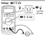
I see Fluke 87 has LPF function for AC power. Compare readings.

With Filter on should be most accurate, the difference is noise.

image.jpg
 

A True RMS meter measures the same voltage for a sinewave, triangle wave, sawtooth wave and squarewave when they all have the same RMS voltage.
A simple meter that peak detects then scales it with x0.707 times for a sinewave measures a different voltage for each waveform.

True RMS meter gives you the Peak Voltage not the RMS voltage?

- - - Updated - - -

see Fluke 87 has LPF function for AC power. Compare readings.

With Filter on should be most accurate, the difference is noise.

why do u have to use the LPF filter when measuring AC line?

If you don't have the LFP filter turned on it will measure a higher AC voltage?
 

True RMS uses a special IC that does the Root-Mean-Squared. It does not peak detect then scale down to 0.707 times for a sinewave like a simple meter.

Power line noise is higher frequencies than 60Hz. A filter in the meter can be switched on so it removes the noise so it is not included in the measurement.
If you measure 140V RMS without the filter and 120V with the filter then there is 20V of noise which is a lot.

EDIT: I had a Fluke 87 meter about 30 years ago. Maybe yours measures wrong because it is old and needs to be re-calibrated.
 

Power line noise is higher frequencies than 60Hz. A filter in the meter can be switched on so it removes the noise so it is not included in the measurement.

Do you need to use the LPF filter when measuring 120vac at 60hz wall outlets?

True RMS uses a special IC that does the Root-Mean-Squared.

So the reading is RMS or peak?

I'm confused about True RMS compared to a meter that is RMS, they both display an RMS voltage


It does not peak detect then scale down to 0.707 times for a sinewave like a simple meter.

This displays an RMS voltage

There is a voltage peak detect circuit , plus an IC chip or Microprocessor that does the 0.707 formula

But only works for sinewaveform , because the RMS for squaveform and triangle or other waveforms don't use the same formula at 0.707
 

Do you need to use the LPF filter when measuring 120vac at 60hz wall outlets?
I have never had power line noise so I never needed a filter.

So the reading is RMS or peak?
I'm confused about True RMS compared to a meter that is RMS, they both display an RMS voltage
A true RMS meter shows the actual RMS voltage for many different waveforms. A simple meter peak detects then multiplies it by 0.707 and guesses that the input is only a perfect sinewave.

A true RMS meter does not simply peak detect, instead it uses a special IC that calculates true RMS for almost any waveform.
A simple meter does not use an IC or microprocessor to multiply by 0.707. Instead it simply uses 2 resistors as an attenuator.
 

I believe the Fluke 87 samples at 50kHz max rate for true RMS and computes root of squared samples.

An average mode DMM measures the DC peak voltage and does 2 samples per second.

I wonder if you asked the maintenance staff about the high level increasing their energy costs. If they have a dedicated transformer, a tap change is indicated to bring within 10% nominal or to survey the loads for phase balance.

An LPF is required for dirty power, such as tri-level solar inverters.
 

Status
Not open for further replies.

Part and Inventory Search

Welcome to EDABoard.com

Sponsor

Back
Top