Continue to Site

Welcome to EDAboard.com

Welcome to our site! EDAboard.com is an international Electronics Discussion Forum focused on EDA software, circuits, schematics, books, theory, papers, asic, pld, 8051, DSP, Network, RF, Analog Design, PCB, Service Manuals... and a whole lot more! To participate you need to register. Registration is free. Click here to register now.

[PIC] Basic pic programming & wiring Q

Status
Not open for further replies.

Veketti

Full Member level 3
Joined
Sep 14, 2014
Messages
164
Helped
0
Reputation
0
Reaction score
0
Trophy points
16
Activity points
1,700
Dear All,

On analog circuit thread I asked about injector pulser which I created by using 555 chip. Now I want to step to microcontroller world as I find it fascinating. I've done some c-programming (not embedded) about 14 years ago so why not give it a go. I ordered pickit 2 starter kit and few 12F683 chips. I was planning to create injector pulser which uses PWM and has variable on time selection by button. I have few doubts which I haven't found answer yet. Firstly I see that I should use external chrystal for oscillator. If I've understood right this chip does have one built in? This external chrystal does 4MHz work? This is what I don't quite understand what freq should it be..
Second, should the button pull input pin to ground to work or +5VDC?
Thirdly, I'm only able to go down to 250Hz on frequency for the PWM. Tried to search this from datasheet but didn't succeed. Is there any other way to have eg.30Hz as frequency?

Last but not least as I'm not familiar with the embedded systems and handling those inputs and outputs are not fully clear to me, am I handling ports right here? I find it hard to understand port initializing like this way: TRISIO = 0x03; so I prefer TRISIO.B0 = 1;, hope it's ok? I'm not sure am I allowed to use all these B0,3 & 2 on this chip or not.

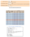
Here's the microC complier code
Code:
        sbit Time_button at GP0_bit;
        sbit Start_button at GP3_bit;
        sbit Output at GP2_bit;
        short times;
        short i;
        long milliseconds;

void InitMain(void) { 
     TRISIO.B2 = 0;        // Set GP2 (pin 5) as output
     TRISIO.B3 = 1;        // Set GP3 as input. Not needed as it's input only?
     TRISIO.B0 = 1;        // Set GP0 as input
     PWM1_Init(250);       // Set 250hZ frequency
     PWM1_set_duty(127);   // set 50% duty cycle

}


void main(void) {
     InitMain();
     times = 1; // Variable how many times button pressed
     while(1){
              if(!Time_button) // When time button is pressed
              {
               if (times > 11) times = 1; // Maximum time for pulsing is 55seconds
               for(i=0 ; i<times ; i++){ // Tell how many seconds * 5 it will pulse by switching solenoid on
                  Output = 1;
                  delay_ms(200);
                  Output = 0;
               }
                 times++;
              }
     
              if(!Start_button)  // When start button is pressed
              {
                 milliseconds = 5*times*1000;  // Convert time to milliseconds
                 PWM1_Start();
                 Vdelay_ms(milliseconds);  // Pulse Output for given time
                 PWM1_Stop();
              }
        delay_ms(10);  // Delay 10ms until next round
     }
}

Sorry for the long post and thank you all in advance for helping me out.
 

the PIC12F683 has an internal precision 8Mhz (and 32KHz) oscillator - you can use this or an external crystal
your button can pull down to 0v or up to +5v so long as your program knows which is button pressed/not pressed

I don't understand what you mean by
Thirdly, I'm only able to go down to 250Hz on frequency for the PWM. Tried to search this from datasheet but didn't succeed. Is there any other way to have eg.30Hz as frequency?

what exctly do you wish to do?
yoi can set/clear the TRIS bits by writing to the whole register or individual bits - it is up to you
 

the PIC12F683 has an internal precision 8Mhz (and 32KHz) oscillator - you can use this or an external crystal
your button can pull down to 0v or up to +5v so long as your program knows which is button pressed/not pressed
Do I have any benefits on using external crystal?

I don't understand what you mean by
Thirdly, I'm only able to go down to 250Hz on frequency for the PWM. Tried to search this from datasheet but didn't succeed. Is there any other way to have eg.30Hz as frequency?
I mean that I'm not able to set any lower frequency for the PWM than 250Hz. This line:
PWM1_Init(250); // Set 250hZ frequency
I would want to have it PWM1_Init(30); but I get compiler error that "Argument is out of range". Why so and any other way to have it 30?
 

Do I have any benefits on using external crystal?


I mean that I'm not able to set any lower frequency for the PWM than 250Hz. This line:
PWM1_Init(250); // Set 250hZ frequency
I would want to have it PWM1_Init(30); but I get compiler error that "Argument is out of range". Why so and any other way to have it 30?

external crystal oscillators tended to be more accurate than the fast RC oscillators used in many microcontrollers. In addition one may require a particular frequency for hardware or timing events, e.g. 7.3728MHz to generate very high baud rates for UARTs. More advanced microcontrollers have clock multipliers and dividers to allow one to generate a range of system and peripheral frequencies

have you read section 11.3 the pic12F683 data sheet to see if it is possible to generate the PWN frequencies your require
https://www.microchip.com/wwwproducts/Devices.aspx?dDocName=en010115

also where did the PWM1_Init(250); etc code come from?
it may be restricted in what it can do. check the documentation
 
It seems you are using mikroC PRO PIC Compiler. I guess it allows PWM frequencies only above 1 KHz or 1.5 KHz, the library functions. I have never generated < 1000 Hz PWM pulses, So, try to configure the CCP registers manually and see if you can get 30 Hz PWM signal frequency.
 
if all else fails you can always generate the PWM using timer interrupts
I recently needed 15 PWM outputs from a PIC24FJ256GB110 which 'only' has 9 hardware PWMs - ended up doing them all in software
 
Fpwm = Fosc / ((PR2 + 1) * 4 * N )

PR2 max = 255
N max = 16 (1, 4, 16)

4 MHz / (256)* 4 * 16 = 244.140625 Hz

With a 4 MHz crystal you can get PWM freq not less than 244.140625 Hz.

If you use 1 MHz Clock then you can get 61 Hz Fpwm.

See if you can use any low frequency Internal Oscillator and get 30 Hz PWM. As mentioned by horace1 you can use Timer interrupts to generate 30 Hz pulses. A PWM of such low frewuency will be of not much use.
 
if you use the internal 8Mhz oscillator with postscaler to get a 250Khz internal oscillator you should be able to get a PWM of 30Hz using a PR2 of of 130?

250000/130*4*16 = 30Hz
 
Re: Basic pic programming &amp; wiring Q

horace1 is faster than me.

Try this code with internal RC OSC.

250 KHz OSC freq is used.


Code C - [expand]
1
2
3
4
5
6
7
8
9
10
11
12
13
14
15
16
17
18
19
void main() {
 
     OSCCON = 0x31;
     //OSCTUNE = 0x0F;
     T2CON = 0x07;
     PR2 = 0x81;
     CCP1CON = 0b00001101;
     Delay_ms(200);
     
     
     TRISIO = 0x00;
     GPIO = 0x00;
     
     PWM1_Set_Duty(127);
     PWM1_Start();
     
     while(1);
     
}


- - - Updated - - -

Here is a webpage with a Calculator to get the PWM registers values.

https://www.micro-examples.com/public/microex-navig/doc/097-pwm-calculator.html


110228d1413104083-pwm-calc.png
 

Attachments

  • pwm calc.png
    pwm calc.png
    58.5 KB · Views: 141
Alright Gents, that "Fpwm = Fosc / ((PR2 + 1) * 4 * N )" seems to be the limiting factor. Is there any harm in making the MCU clock to 0.5MHz (in MicroC Pro, Project settings - MCU Clock - frequency)? This way I can get it down to 31Hz. If I interpret Milan.rajik´s code is it kind of doing the same (at least OSCCON bit6-4)..? Is it ok to alter that as the internal crystal is at 8MHz? Will this "underclocking" affect eg. delay time that eg. 1000ms is still 1second?
 

Re: Basic pic programming &amp; wiring Q

According to my OSCCON settings 8 MHz will be passed through a Prescalar to get 250 KHz clock for PIC. PIC will be slow. If you have other things to do with the PIC, it will be slow.

Is there any harm in making the MCU clock to 0.5MHz (in MicroC Pro, Project settings - MCU Clock - frequency)?

You have to choose INTRCOSC from drop down list but I am not sure whether doing just that will generate the right OSCCON settings. I guess it has to be configured manually. Anyway try your method and compile the code and see the .asm file generated. See if OSSCON is properly assigned the value needed.

- - - Updated - - -

I tested the code generated for 0.25 KHz clock with INTRCOSC but OSCCON register value is not assigned any value. You have to set the OSCCON register manually in the code.
 
Finally got my programmer so the testing began. Unfortunately I'm not able to make it work as it should. It doesn't mind those button presses. When I power on the device it starts the sequence even though inputs are high. It blinks Timerled once and output is on for 5 sec, then blinks Timerled for 2 times and output is on for 10 sec and so on. If I press start button it does start the sequence from beginning. Time button doesn't do anything. It shouldn't even go inside those IF's as both inputs GP3 and GP0 are high. If I remove from those two if clauses the "!", led and output are continuously on. What am I missing? Please somebody help.

Code:
       sbit Time_button at GP0_bit;
        sbit Start_button at GP3_bit;
        sbit Output at GP2_bit;
        sbit TimerLed at GP1_bit;
        short times;
        short i;
        long milliseconds;

void InitMain(void) {
     TRISIO.B2 = 0;        // Set GP2 (pin 5) as Output
     TRISIO.B1 = 0;        // Set GP1 (pin 6) as Output
     TRISIO.B3 = 1;        // Set GP3 (pin 4) as input. Not needed as it's input only?
     TRISIO.B0 = 1;        // Set GP0 (pin 7) as input
     PWM1_Init(500);       // Set 500hZ frequency
     PWM1_set_duty(127);   // set 50% duty cycle

}


void main(void) {
     InitMain();
     times = 1; // Variable how many times button pressed
     while(1){
              if(!Time_button) // When time button is pressed
              {
               if (times > 11) times = 1; // Maximum time for pulsing is 55seconds
               for(i=0 ; i<times ; i++){ // Tell how many seconds * 5 it will pulse by blinking led
                  TimerLed = 1;
                  delay_ms(250);
                  TimerLed = 0;
                  delay_ms(250);
               }
                 times++;
              }

              if(!Start_button)  // When start button is pressed
              {
                 milliseconds = 5*times*1000;  // Convert time to milliseconds
                 PWM1_Start();
                 Vdelay_ms(milliseconds);  // Pulse Output for given time
                 PWM1_Stop();
              }
        delay_ms(10);  // Delay 10ms until next round
     }
}

Btw, that 30Hz works with milan.rajik's code. I just didn't implement it to this yet as I need to get the basics to work.
 

Something like this helps ?


Code C - [expand]
1
2
3
4
5
6
7
8
9
10
11
12
13
14
15
16
17
18
19
20
21
22
if(!Time_button) // When time button is pressed
{
    Delay_ms(50);
    if(!Time_button) // If time button is still pressed
    {
        
    }
 
}
 
 
//or
 
if(!Time_button) // When time button is pressed
{
    Delay_ms(50);
    while(!Time_button); // wait here untill time button is released
    {
        
    }
 
}

 
This will turn output continuously on. Time button press does nothing. Could it be that there is some setting which is causing this?
 

Explain in detail how the system should work when each button is pressed. Zip and post mikroC project files.
 
This is supposed to have PWM output on for 5,10,15...55 seconds on GP2 when GP3 input is pulled to ground. If button which pull GP0 to ground is pressed time is added 5 seconds in every button push. Every button push will blink led in output GP1 as many times as pushes are registered. Eg. 5 pushes blink led 5 times and 5 blinks sets the time 5x5seconds = 25seconds.

Say I want to have GP2 on for 20 seconds, I push timer button for 4 times. I get four blinks of led and when I press start button, GP2 is on with PWM output for 20 seconds.

View attachment test.zip
 

How are you testing ? In Proteus or hardware ? Try attached code in hardware and reply.
 

Attachments

  • test.rar
    56.7 KB · Views: 82
There was a small error. I have fixed it.
 

Attachments

  • test rev1.rar
    56.8 KB · Views: 85
Alright, you seem to rewrote the code. Added these to my original code:
Code:
ANSEL = 0x00;
CMCON0 = 0x07; 
GPIO = 0x00;
And used the project files that you included (deleted Test.c and pasted my code there) and it works! Now I'm wondering that what was wrong on my project files and settings? Understanding this is important to me so that I can continue with new challenges.


Thank you
 

Analog function on pins had to be disabled so that the pins work as digital IO pins. Digital input pin for buttons and digital output pin for PWM (CCP1). Comparator function had to be disabled otherwise pins with Comparator input would work as Comparator enabled.

I will soon post a new code in which only one Timer (Timer1) will be used. I have used Timer0 to get a delay of 2 seconds when button is pressed. If you press button to increment times then it should not immediately start executing the code because there might be another increment of times by pressing the button. So, if you press button then it increments times and waits 2 seconds before start blinking the LED. If there is another press within 2 seconds after first press of button then times is again incermented and the system waits 2 seconds after the last button press and then starts executing the blink code.
 
Last edited:
Status
Not open for further replies.

Similar threads

Part and Inventory Search

Welcome to EDABoard.com

Sponsor

Back
Top