Continue to Site

Welcome to EDAboard.com

Welcome to our site! EDAboard.com is an international Electronics Discussion Forum focused on EDA software, circuits, schematics, books, theory, papers, asic, pld, 8051, DSP, Network, RF, Analog Design, PCB, Service Manuals... and a whole lot more! To participate you need to register. Registration is free. Click here to register now.

[SOLVED] LCD initialization witout using inbuilt function of MIkroC

Status
Not open for further replies.

shubham kumar

Member level 3
Joined
Sep 11, 2014
Messages
59
Helped
1
Reputation
2
Reaction score
1
Trophy points
8
Location
bangalore
Activity points
511
I am using PIC18F452 and MikroC

I have tried numerous ways to initialize LCD without using the inbuilt functions of MikroC, but can't get through.

I came up to this solution from a very old post on the forum
(https://www.edaboard.com/threads/259769/),
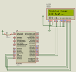
but I am not getting the correct output. It is showing some characters on LCD but not exactly what I sent

Code:
#define LCDP PORTB
sbit LCD_RS at LATD6_bit;
sbit LCD_EN at LATD7_bit;
sbit LCD_D4 at LATB4_bit;
sbit LCD_D5 at LATB5_bit;
sbit LCD_D6 at LATB6_bit;
sbit LCD_D7 at LATB7_bit;

sbit LCD_RS_Direction at TRISD6_bit;
sbit LCD_EN_Direction at TRISD7_bit;
sbit LCD_D4_Direction at TRISB4_bit;
sbit LCD_D5_Direction at TRISB5_bit;
sbit LCD_D6_Direction at TRISB6_bit;
sbit LCD_D7_Direction at TRISB7_bit;


void cmd(void);

void lcd_dat(void);
void LCD_ini(void);


void main(){
int j=0;
char ldg[6]="MiKroC";
    TRISD=0X00;
    PORTD=0X00;
    TRISB=0X00;
    PORTD=0X00;
    LCD_init();
    for(j=0;j<=5;j++)
    {
            LCDP=ldg[j];
            lcd_dat();
    }
    while(1){

    }
}

void LCD_ini(void){


     LCDP=0X28;        //using5*8dots
     cmd();
     LCDP=0X0C;        //display ON
     cmd();
     LCDP=0X01;        //clear lcd//
     cmd();
     LCDP=0X86;        //intial cursor position//
     cmd();
}

void cmd(void){
    LCD_RS=0;
    LCD_EN=1;
    delay_us(500);
    LCD_EN=0;
    delay_us(500);
}

void lcd_dat(void){
    LCD_RS=1;
    LCD_EN=1;
    delay_us(500);
    LCD_EN=0;
    delay_us(500);
}

I tried like, giving ASCII value directly, 4bit mode/8bit mode/ defining like #define DISPLAY PORTB
#define LCD_RS PORTD.B6
#define LCD_EN PORTD.B7

but I think it was just permutation-combination, I might be missing some basic concept.
 

Here is my LCD code. See if that works for you. I have created LCD library similar to mikroC LCD library. Uncheck the LCD library in library manager before using my code. I have tested this in both Proteus and hardware and it works.

change this

Code C - [expand]
1
char ldg[6]="MiKroC";


to this

Code C - [expand]
1
char ldg[7]="MiKroC";


or better


Code C - [expand]
1
char ldg[]="MiKroC";


https://www.edaboard.com/threads/290093/

110076d1412692638-lcd.png


- - - Updated - - -

You are using 4 bit mode for LCD, so, you have to send data and command as two nibbles (upper and lower nibbles).
 

Attachments

  • PIC18F452 LCD.rar
    113.7 KB · Views: 85
  • lcd.png
    lcd.png
    35.4 KB · Views: 138
Last edited:
Thanks milan.rajik

I was also trying to make the LCD_OUT function but couldn't get through the simple ones :D .. but this helped a lot.
thanks again.

- - - Updated - - -

That is working perfectly (other than I changed name of some functions as they were already available in MIkroC library).

But I have some doubts in that:
1) Inside LCD_init function why the results are not clear if I replace the //LCD RESET block// with commands "LCD_cmd(0x33) and LCD_cmd(0x32)"

- - - Updated - - -

oh sorry ... It is functioning superbly if one replace the //reset area// in //LCD_Init()// function by these two commands.
 

I didn't get what you are saying. Where is reset area in LCD_Init() ?
 

I didn't mentioned it correctly. I was talking about the code between // Reset process from datasheet // and // Reset Process End // in LCD_init function.
this whole can be replaced by these two LCD_cmd(0x33) and LCD_cmd(0x32).
I read about this while searching on google but at that time I didn't understood their use. But when I experimented it with your code things got clear.

(your code does the same at bit level, I mean you are assigning value to each bit in LCD_init(), whereas this will be done in LCD_cmd so we can make this short by just giiving LCD_cmd(0x33) and LCD_cmd(0x32) in place of code between //Reset Process// tags.)
 

Yes, you can do that. I initially wrote LCD_Init() function and then made the LCD_Cmd() and LCD_Out() functions. Hence the code is like that.

Here is another LCD 4 bit code. http://www.embeddedcraft.org/lcd4bit.html

In my code you can use any pin combination for LCD Data and LCD Control.
 
Last edited:

@milan.rajik

As I am a bit weak in programming, I have one question in the code.

I just bit played with your functions and I made it like this
Code:
void LC_dat(unsigned char k){

    PORTB= (k & 0xF0);        // sending higher nibble
    LCD_RS=1;
    WAIT

    PORTB= ((k & 0x0F)<<4);       // sending lower nibble
    LCD_RS=1;
    WAIT
}
  void LC_out(unsigned char row,unsigned char col, const char *str )
  {
    switch(row) {

         case 1: LC_cmd(0x80 + col-1); break;
         case 2: LC_cmd(0xC0 + col-1); break;
         default: LC_cmd(0x80 + col-1);break;
                }
     while(*str)
       LC_dat(*str++);

}
In the function----
Code:
void LCD_out(unsigned char row,unsigned char col, [B]const[/B] char *str )
what is the significance of the word "const", I mean what does it do.

for example if I use your function and give parameters as
Code:
  LCD_out(1,8,"miKRoc");
then it works superbly.
But if I give
Code:
Int p=3000; unsigned char txt1[16];
        IntTostr(p,txt1);
        LCD_out(2,1,txt1);
It does not work.

But if I change the function to
Code:
 void LCD_out(unsigned char row,unsigned char col, char *str )
then
Code:
Int p=3000; unsigned char txt1[16];
        IntTostr(p,txt1);
        LCD_out(2,1,txt1);
It works.

Can you explain me the significance of const.
I think that it stands for constant but the parameter value we are passing is different everytime.
In short, I didn't got it.

Thanks again.
 

const char are stored in ROM and frees RAM for other work. If you have a lot of strings in a project then you can store them in ROM but then you have to use CopyConst2Ram() function. Search for CopyConst2Ram in mikroe forum.

I just bit played with your functions and I made it like this

If you do like that then you have to use upper 4 bits of a PORT for LCD data. In my version you can use any combination of pins for LCD data and control like you can use RB0, RC1, RD3, RE2 for LCD Data and RB4, RE1 for LCD Control.
 

Status
Not open for further replies.

Similar threads

Part and Inventory Search

Welcome to EDABoard.com

Sponsor

Back
Top