Continue to Site

Welcome to EDAboard.com

Welcome to our site! EDAboard.com is an international Electronics Discussion Forum focused on EDA software, circuits, schematics, books, theory, papers, asic, pld, 8051, DSP, Network, RF, Analog Design, PCB, Service Manuals... and a whole lot more! To participate you need to register. Registration is free. Click here to register now.

use of ferrite core transformer

Status
Not open for further replies.

Briez

Member level 5
Joined
Nov 30, 2012
Messages
83
Helped
4
Reputation
8
Reaction score
4
Trophy points
1,288
Activity points
1,835
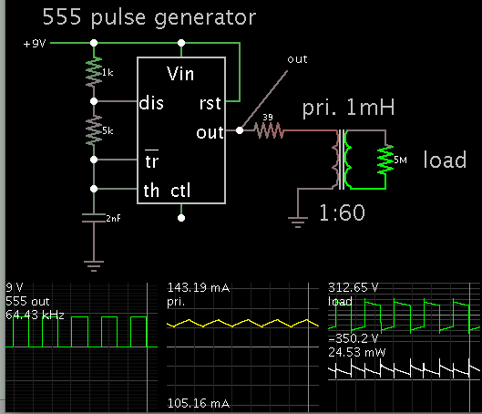
I want to use a ferrite core transformer for voltage step up to 250v from 5v dc.

I have one sample of it, it display primary winding of 004ohm and secondary at 030ohm. But how it can be contacted to step up voltage?

I need circuit to operate it and also want to know it's principle of operation.
 

A ferrite cored transformer works best at medium frequencies and certainly not DC so you need to convert your 5V DC to at least 5V AC at maybe 50KHz before the transformer will work. It can be a difficult topic and not easy to explain in a few words. Do some research on SMPS (Switch Mode Power Supply) for ideas on how it works.

Brian.
 

Thanks for reply.

I want to know that what should fed into primary of ferrite core transformer?

Can I apply 555 timer generated square wave frequency output in primary ?
 

Yes you can but the results may not be as you expect. The 555 can only supply a relatively small current and the maximum power it can drive into the transformer will be limited to approximately the 555 supply voltage multiplied by that current. What you get out of the transformer will depend on the ratio of turns on the primary (555 side) and secondary sides. It will step the voltage up if there are more turns on the secondary but it will not give you more power. In fact it will be quite a lot less than you put in to it.

Example: 555 produces 100mA at 5V output so the power to the transformer is (0.1 * 5) = 0.5W.
If the secondary had enough turns to step the voltage up to 250V, and the transformer is say 70% efficient, the output power would be (0.5 * 0.7) = 0.35W but you would only be able to draw 1.4mA from it.

Brian.
 

Yaa that's right.

So how can I apply my direct supply with 50hz frequency?

MY ferrite core has 50 turns in primary and 250 on secondary.


Actually I am working on the high voltage spark igniter project. I found the circuit and got ferrite core transformer for it. But I don't know how this circuit work.

Here is the circuit. **broken link removed**
 
Last edited:

This simulation demonstrates how a 555 IC could drive a transformer directly.


Without the 39 ohm resistor, current rises to a level which would cause the 555 to overheat. Some resistance may be in the transformer as well.

The EngineersGarage project is more complicated. They call it a 'capacitor discharge ignition system'. It has two transformers.
 

The engineersgarage design won't work anyway. It relies on the battery being poor to work at all and with a good supply it will do nothing.

Brian.
 

Status
Not open for further replies.

Similar threads

Part and Inventory Search

Welcome to EDABoard.com

Sponsor

Back
Top