Continue to Site

Welcome to EDAboard.com

Welcome to our site! EDAboard.com is an international Electronics Discussion Forum focused on EDA software, circuits, schematics, books, theory, papers, asic, pld, 8051, DSP, Network, RF, Analog Design, PCB, Service Manuals... and a whole lot more! To participate you need to register. Registration is free. Click here to register now.

Which of these two circuits is more reliable?

Status
Not open for further replies.

Jester

Full Member level 6
Joined
Aug 18, 2012
Messages
377
Helped
7
Reputation
14
Reaction score
7
Trophy points
1,298
Location
.
Activity points
4,754
uController running on +5V, needs to source approximately +12V to a 250 Ω resistive load via 4' of wire. End user will make connection assume no ESD precautions will be taken by end user.

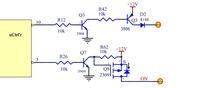
Two circuits shown, which of the two do you think would be more reliable (top or bottom)?


Both will work, personally I would use the top one but add a resistor between the second Q3 base and emitter to ensure it turned off when the first Q3 stopped conducting.

With a resistive load, both are OK but if anything stores charge at the output, the second circuit may be prone to damage due to high reverse voltage across the gate/source of the MOSFET.

Brian.
 
I think that a power driver IC would be much more able to
withstand ESD-type abuse than any discrete device, and
since your lashups involve multiple discretes you might end
up money ahead using one of the lower-drive-current ones.
Now whether the open-collector type drive is necessary
or just simplicity, I couldn't say, nor whether using a driver
with source and sink is tolerable. There are some FET drivers
with independent go-low and go-high output legs, if needed.
 

I would go with top cct and get the 3904 and 3906 complementary like the mmdt3946. BJTs are inherently robust to ESD, typ. 400V MM and 4kV HBM.

As suggested above, add a resistor between base and emitter on PNP to ensure it is turned off.

Otherwise, you could use digital transistors, Pre-Biased Transistors, with the resistors integrated into the chip. See for instance DCX114EK.
 

I think that a power driver IC would be much more able to
withstand ESD-type abuse than any discrete device, and
since your lashups involve multiple discretes you might end
up money ahead using one of the lower-drive-current ones.
Now whether the open-collector type drive is necessary
or just simplicity, I couldn't say, nor whether using a driver
with source and sink is tolerable. There are some FET drivers
with independent go-low and go-high output legs, if needed.

I tried using a FET driver for that purpose once: https://www.digikey.ca/product-detail/en/ZXGD3003E6TA/ZXGD3003E6TR-ND/1827735
and found that the output would only go to full Vcc voltage for a few hundred ns and then go down to about 1/2 voltage after that. There was nothing on the data sheet to indicate that the device would do that.

You refer to the ZXGD3003 - this is totem pole NPN-PNP emitter follower. Just like all the other ZXGD30xx series. These are designed to drive capacitive loads, not resistive loads.
 

I would go with top cct and get the 3904 and 3906 complementary like the mmdt3946. BJTs are inherently robust to ESD, typ. 400V MM and 4kV HBM.

As suggested above, add a resistor between base and emitter on PNP to ensure it is turned off.

Otherwise, you could use digital transistors, Pre-Biased Transistors, with the resistors integrated into the chip. See for instance DCX114EK.

juicedry,
Good idea, one less part (or perhaps 5).


- - - Updated - - -

You refer to the ZXGD3003 - this is totem pole NPN-PNP emitter follower. Just like all the other ZXGD30xx series. These are designed to drive capacitive loads, not resistive loads.

dickfreebird,

Can you suggest a resistive load driver (that can source 100-200 ma @12V)?


Thank you for your sharing your ideas.

This is a great forum
 

Load switch circuit. With increasing current you want an PNP or PMOS with greater current handling. Like the MMDT2227M.
 

None of these designs have protection for ESD, current limit, short circuit recovery, thermal protection.

My suggestion would be a smart protected Automotive rated switch.
1 Ohm on resistance will drop 0.2V with 200mA and dissipate less than a 1/4W.

$1.27 in qty 1.
SOT223-3L.jpg
 

Status
Not open for further replies.

Part and Inventory Search

Welcome to EDABoard.com

Sponsor

Back
Top