Continue to Site

Welcome to EDAboard.com

Welcome to our site! EDAboard.com is an international Electronics Discussion Forum focused on EDA software, circuits, schematics, books, theory, papers, asic, pld, 8051, DSP, Network, RF, Analog Design, PCB, Service Manuals... and a whole lot more! To participate you need to register. Registration is free. Click here to register now.

Modifying a simple shock box diagram.

Status
Not open for further replies.

Johanx2

Advanced Member level 4
Joined
May 13, 2012
Messages
113
Helped
1
Reputation
2
Reaction score
1
Trophy points
1,298
Activity points
2,636
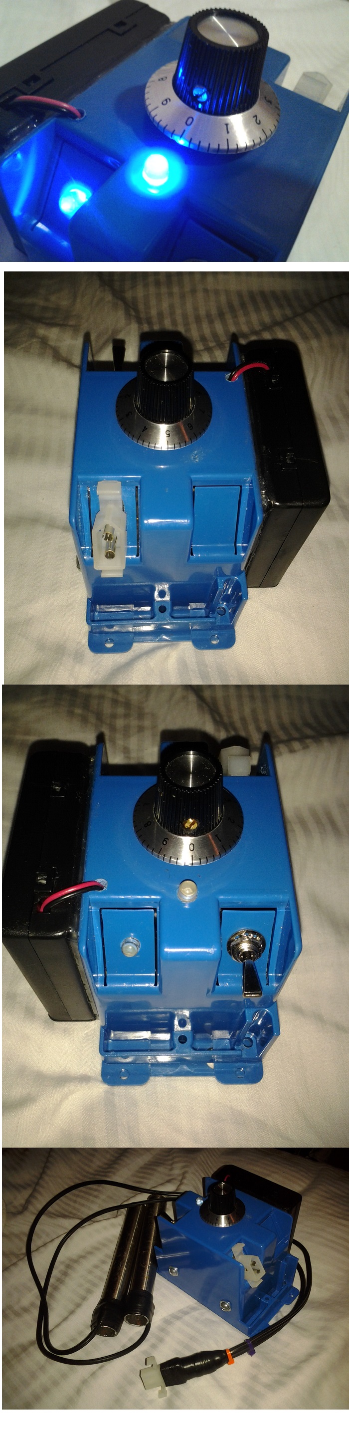
Hello everyone. As many of you may know, this is a very popular diagram to build a shock box. What is a shock box ? It basically is a box that has two electrodes and a potentiometer to control the intensity. the user take the two tubes in order to feel energy passing through the arms and body. It does not hurt, it does feel like when your arm or leg is numb, so this is not intended to hurt people/self defense, it's something to get funny with friends or family.

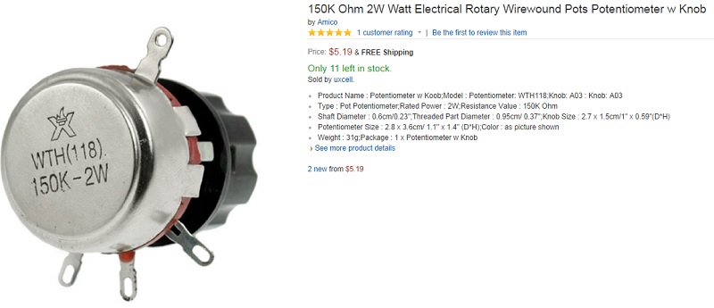
Ok, I am posting this because I have noticed how the potentiometer does not last too much, it burns after some days of use. I think that it's not a good idea using a potentiometer to limit the energy that the "primary" gives, because the potentiometer is directly getting all the load. Just see at the audio amplifiers, there's no any potentiometer directly controlling the output. So what I want to do is to remove the potentiometer of the diagram that you see below, and just control the intensity level varying the power source using a variable power supply (0 to 9v for example). I know that it's not that easy and I will need to change the transistor and the resistor, or what do you suggest ? using a circuit with triacs similar to "lamp dimmers" in order control the current between the user and the transformer ? I tried a dimmer but it did not work. Can you suggest something ? I am surprised to see that this is a very popular diagram and nobody has made a better circuit.


sdfsd.jpg


Edited: Finally, this is how my shock box looks. Isn't nice ?
2431835300_1413598199.jpg
 
Last edited by a moderator:

It is not a good way using a dimmer because you will have no load actually. If you do the circuit with triacs then you will nee triggering circuit and will not be simple as this.

The easy way is, measure the AC (RMS) voltage across the 100k pot and find the power dissipation by
Code:
V * V / 100,000
( because actually there is not going to be any load out of the pot terminals (already its a good choice) )
and with that power dissipation you can choose a pot which will not burn out.

If you want to make the pot more reliable and want to reduce the cost of the pot you can increase its value upto 500k
It will reduce the power rating so that the cost.
 

Thanks, then it's ok having a potentiometer there ? I think that 500k instead will not change anything, I think that I need to use a potentiometer bigger in "watts". Those that I have been using are 0.5w, what if I use something bigger than that ? for example 3 or 5 watts ? Will it last more ?
 

The way to control power is to vary the dwell time on inductive transformer. P = 1/2LIp^2 where Ip=V*dt/L and dt is pulse duration. Thus I think P=1/2(Vdt)^2/L. Then no pot required on output, just input recurring 1 shot time.
 

I think this project is very dangerous and might kill somebody who has a weak heart that is unknown to be weak.
The victim holds an electrode in each hand so the current goes through the heart. The current is limited by the victim's skin resistance that is high when dry but is fairly low when sweating or into a wound.
Low resistance causes high current. It does not take much current to kill a healthy person and it takes much less current to kill a weak person.

Please find a project that is safe and useful instead.
 

Those that I have been using are 0.5w, what if I use something bigger than that ? for example 3 or 5 watts ? Will it last more ?

You have to find the voltage across the pot fixed terminals to find its power rating the formula is
( transformer output Voltage) * ( transformer output Voltage) / resistance of pot
also you should not do short circuit the electrodes, that is a easy cause of damaging the pot.

Then no pot required on output, just input recurring 1 shot time.
Leaving the transformer terminal open is more more dangerous.
 

Ok I have just started the experiment. The idea is to remove that potentiometer at the output and control the intensity by varying the input voltage with a variable power source. 1.2v to 6v, thanks to IC-LM317. By they way, the circuit that you can see at the first message, is not energy efficient, given the fact that it is always at maximum intensity, just the pot limiting the current at the output. Then if I control its intensity by varying the power source, we can say that we are using only the requested energy, so we will save energy!.

I just removed the led, so I can feed the circuit with less voltage. I kept the resistance because it's necessary, I saw how the circuit did not run with out the resistor, the tip31 did not get burn. So is it really necessary having that resistor there ? Does anybody know what is the minimum value of that resistance in order to make the circuit run ? although I said, it seems like the tip31 does not burn without that resistor. Sorry for bad grammar, English is my second language.
 

The 560 ohms series base resistor limited the base current of the transistor and the LED current. Since you removed the LEDs and replaced them with wire then the voltage across the 560 ohms resistor is higher then the base current is higher. Do not change the resistor.
 

I have something curious to say related to electronic. It's about that diagram that today is abruptly burning my poor potentiometers, which is something weird for me since I made this same project several years ago and everything went perfect, not just like today that I got smoke, the noise of something burning, and the odor of a burned electronic component. "Ha Ha".

Today, thinking in why not making my own potentiometer "specially designed for this", I realized that doing that it's ok, but I should for a while first try to modify the 0.5w pot that is burning out. Just because I just concluded that this is a new type of potentiometer, where its internal wiring or metal parts are holding a design that cause a type of short circuit, not direct, it's just that the energy of these electrodes tends to jump each other, making an energy bridge. The old pots had a design where there were less internal wiring and a simpler design, not just weird like nowadays!
 

Since he is talking about "energy of the electrodes jumping each other" then the voltage is thousands of volts which is arcing. Pots are not designed for thousands of volts so of course there is arcing and smoke.
A level control pot should be at The Input of a high voltage circuit, not at the output.
 

but 1000v on 100k is about 10w power ful can kill a person in matter of milli secs, no cap to make a pulsing effect..

the safest continuous voltage for human body is maximum 80v. may be turns on the pot are so closer may be there is not enough insulation to withstand the voltage. Then a specially designed pot only will satisfy the purpose.
 

Hi everyone. I am going to try to add some info, so it maybe will answer some doubts. Few days ago I tried to measure the AC of the electrodes, but my yellow cheap multimeter did get burn, it still works but now I am getting totally wrong values for DC and AC. It did burn not because there was too much energy, but because this energy tends to arc with everything. The size of the arc is too short, for that reason I think that there are about 100v-130v of AC. Few years ago, six friends and I did play with this circuit, I took an electrode and another friend took the other, then we all took our hands in order to close circuit, I remember that everyone could feel a lot of energy passing through body, it was so extreme, but we could easy tolerate it, you know, it was just funny. I can feed this circuit with 3 or 4v, and I will not have the problem of the potentiometer, the V at the output will be enough for shock one or two persons, but I still persist feeding the circuit with 6 or even more V (even 9v) because I want to have the option where even 20 persons can close circuit with the electrodes and still feel a strong power passing through bodies. We are not talking about electrocution, trust me, people tends to get funny with these things, which I found very interesting for parties and all kind of e vents where there are many people. Before designing a proper pot, I will try to buy from amazon a pot that is 100k and at least 2W. I did find some 5W rated, which is more convenient, but they are multi turn, which I found not proper for my project.

PS. I tried controlling the intensity from the input using a variable power supply, but I found that it did not work correctly, given the fact that we get some important AC with the minimum necessary DC that we need to excite and feed the circuit. I can also combine both things, the variable power supply and the pot at the output, so I can feed the system with less voltage when high power is not demanded.
 
Last edited:

I am about to buy a pair of these, what a great price and 2w/wire bound.

8735724300_1412804317.jpg
 

If you show us the datasheet of the transformer you used then we can easily calculate the output voltage.

What is the maximum allowed voltage between parts of the 2W pot?
The problem with a pot at the output is that when it is turned down to halfway with a load then only half of it is used so the rating of a 2W pot becomes 1W.
Half of 150k is 75k ohms. 1W into 75k ohms is a voltage of only 274V. But the circuit might produce 1000V or more.
 

Audioguru, well, I just have bought two of those potentiometers. they seems to be a lot stronger than those that radioshack sells (carbon based and 0.5w). Please notice that they are wire wound made, not carbon, so I believe that I will have a better result with them. I also bought a pack of some multicolor blinking leds, I knew that there were blinking leds in the market, but not with multicolor transitions.
 

Many cheap solar garden lights use fading multicolor LEDs.
Last week I purchased a cheap Halloween clear scull with multicolor LEDs inside. The colors flash, fade, chase or turn off each time a selector button is pressed.
 

Many cheap solar garden lights use fading multicolor LEDs.
Last week I purchased a cheap Halloween clear scull with multicolor LEDs inside. The colors flash, fade, chase or turn off each time a selector button is pressed.

The leds that I am talking about don't need to be connected to any integrated circuit in order to fade or blink, its like each one has it's own embedded IC, which I found really interesting :).
 

Status
Not open for further replies.

Part and Inventory Search

Welcome to EDABoard.com

Sponsor

Back
Top