nicksgoldsmith
Newbie level 1
here i have attached pdf file for strain monitor typ kl66 module(the product of digi sense)
plz find attachements for this,and sir, in the technical specificartion of this transducer they have written that ,signal 12000-18000 hz (5v ttl)
so...my question is how could i measure and calibrate this o/p frequency with using frequency counter
and the measure problem i found that this o/p frequency range is too much for conditioning.
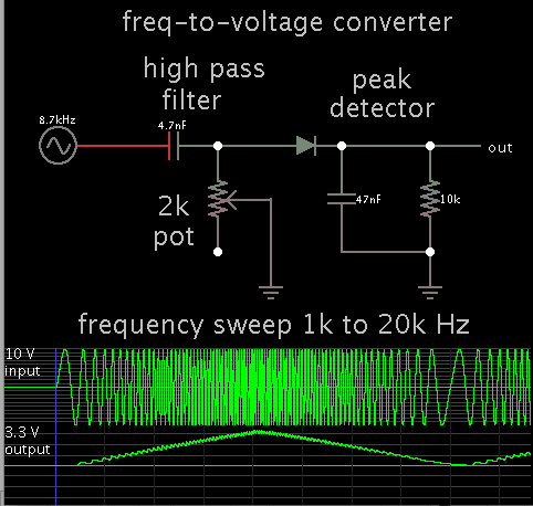
and is it convenient to convert this o/p in voltage by using frequency to voltage converter ?and then calibrate the voltage for load?
again the problem is i didn't found the simple circuit for conversion of f to v for high frequency means--(to convert 12000-18000hz in to the voltage)
(*we r using this transducer for load measurement in elevator)
so...plz give me exact and total solution and if possible give me the simple circuit solution .
thank you,
Regards,
Nikhil.
plz find attachements for this,and sir, in the technical specificartion of this transducer they have written that ,signal 12000-18000 hz (5v ttl)
so...my question is how could i measure and calibrate this o/p frequency with using frequency counter
and the measure problem i found that this o/p frequency range is too much for conditioning.
and is it convenient to convert this o/p in voltage by using frequency to voltage converter ?and then calibrate the voltage for load?
again the problem is i didn't found the simple circuit for conversion of f to v for high frequency means--(to convert 12000-18000hz in to the voltage)
(*we r using this transducer for load measurement in elevator)
so...plz give me exact and total solution and if possible give me the simple circuit solution .
thank you,
Regards,
Nikhil.