Continue to Site

Welcome to EDAboard.com

Welcome to our site! EDAboard.com is an international Electronics Discussion Forum focused on EDA software, circuits, schematics, books, theory, papers, asic, pld, 8051, DSP, Network, RF, Analog Design, PCB, Service Manuals... and a whole lot more! To participate you need to register. Registration is free. Click here to register now.

motor and L293DNE problems

Status
Not open for further replies.

Disha Karnataki

Full Member level 5
Joined
Jul 20, 2013
Messages
249
Helped
9
Reputation
18
Reaction score
8
Trophy points
18
Location
india
Activity points
2,231
i have a l293dne & i have connected it to my microcontroller as shown:

https://3.bp.blogspot.com/-7QojImEY...jddXMw/s1600/motors-to-l293dne-to-arduino.png

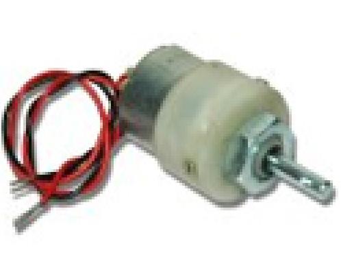
battery is 18v (two 9v battery in series) also tried using 9v .The voltage produced across the pins (3 & 6 for right wheel motor & 11, 14 for left wheel motor as per above image) is perfect i.e around 9v is produced the motor i am using is as here:


they can operate from 9v-12v.
the pins of l293dne produce exactly 18v but, these motors do not rotate.
But when i separately connect battery with motor it runs.
when i connected a led it litted up even when i connected a motor of 3-5v it also worked properly.
But these motors(as in image) are not running what may b the reason?
 
Last edited by a moderator:

Your motor is designed to be powered from only 3V (on its label) so why did you try 9V and 18V?
The maximum allowed output current of the L293 is only 1A so your motor with no maximum current spec probably overloaded and blew up your L293 IC.
A little 9V battery cannot supply much current so maybe its voltage dropped too low when it tried to power the motor.
 

Your motor is designed to be powered from only 3V (on its label) so why did you try 9V and 18V?
i actually ordered for 9v motor & it indeed runs on 9v & above (not on 3v).
The maximum allowed output current of the L293 is only 1A so your motor with no maximum current spec probably overloaded and blew up your L293 IC.
no this is unlikely to have had happened because:
i connected two 9v batteries =18v supply to L293DNE and then connected 12v motors like this one:

2852562700_1412040261.jpg


they ran properly not a problem so the ic is in good condition. But, the motors (in previous post image shown) could not run even after giving proper supply across them.
 
Last edited by a moderator:

i actually ordered for 9v motor & it indeed runs on 9v & above (not on 3v).
Then why did you post the photo of a 3V motor?

i connected .... 18v supply to L293DNE and then connected 12v motors like this one:....
they ran properly not a problem so the ic is in good condition. But, the motors (in previous post image shown) could not run even after giving proper supply across them.
Your photos of motors do not say how much current they use. The maximum allowed current from the L293 is only 1A.
You do not know how much current the original motors use so maybe they overloaded the L293. Maybe you are lucky that the L293 did not burn out.
 

ok i apologize for giving that image & i have actually got them from the haptic arm workshop i have enclosed file below @ page 3 of that file you can see the motors & @ page 9 you can see 9v battery used.
now i have replaced L293DNE ic & i am using motors(as shown in file) i am also powering the ic with 9.43v( open circuit voltage) and i am getting o/p voltage at the pins(3& 6 , 11& 14 of L293DNE) around 9v(approx) good to power those motors but, they are not rotating at all...
 

Attachments

  • Haptic Kit Assembling.pdf
    4.1 MB · Views: 60

The kit assembly instructions and the photos of the motor have no specifications about how much current the motor uses.
The open circuit voltage is useless when it is used to drive a motor. You need the voltage when it drives or when it tries to drive the motor.

The datasheet for the L293 shows that with a supply that is 9V (actual voltage when driving a 1A motor) then the voltage to the motor is typically only 6.4V. Your voltage is much higher.

Maybe you and your Arduino do not understand that for the motor to run then the inputs and outputs of the L293 must be opposite, one is high and the other is low then the motor will have voltage across it.
For the motor connected to pins 3 and 6 the inputs pin 2 and pin 7 must have one input high and the other input must be low.
first of all you did not read my #1 post properly..
i told you already that i have connected an led(in my post #1) it worked properly for the led, without having voltage across the 3& 6 pin ,11 & 14pin of L293DNE ic how could my led's lit up? Now here what is the problem with programing
when i have checked for proper working in simulation & have then executed on hardware there is absolutely no problem with the programing...
i have already mentioned from my post #1 that i am getting enough voltage difference to drive the motor but motor is not rotating... & if i try it with my led's leds are litting up.
 

Your first post has a link that does not work and it is confusing when you said you used an 18V battery and also tried 9V. You said you had 9V across the motor? That is impossible. With an 18V supply the motor should have about 15.4V across it, not 9V. With a 9V supply the motor should have 6.4V across it, not 9V.

You did not say the voltage to ground on pin 3 and the voltage to ground on pin 6 when the L293 is trying to run the motor. Also we need to know the supply voltage when that happens.
If you connected a 5mm 1.8V red LED or a 5mm 3.5V blue or white LED between pin 3 and pin 6 and it did not burn out then something is wrong with your L293 or the battery. A 5mm LED produces some light when its current is only about 1mA. A motor might not run when its current is less than 100mA or 200mA.

Maybe the program produces PWM which can light an LED but not run a motor.
 

Your first post has a link that does not work and it is confusing when you said you used an 18V battery and also tried 9V. You said you had 9V across the motor? That is impossible. With an 18V supply the motor should have about 15.4V across it, not 9V. With a 9V supply the motor should have 6.4V across it, not 9V.
yes you are correct these are actual readings i had to mention it in more elaborate way.. i apologize....

Maybe the program produces PWM which can light an LED but not run a motor.
i shall post my sub program (made only to run motor)
Code:
declaration:
int motorstatehigh=HIGH;     //to send 1
int motorstatelow=LOW;       //to send 0
const int m1=9;             // to  pin  2 of driver 
const int m2=10;            //to  pin 7 of driver 
const int m3=6;            //to  pin 15 of driver  
const int m4=5;          //to pin   10 of driver  
///////////////////////////////
initialization:
  pinMode(m1, OUTPUT);     
    pinMode(m2, OUTPUT);    
     pinMode(m3, OUTPUT);     
      pinMode(m4, OUTPUT); 
////////////////////////////////////////////
code only to run motor:
if(some condition..satisfied)        //run motor till  condition is true
      digitalWrite(m1,motorstatehigh);    //making   pin 2& 15 of driver ic high
      digitalWrite(m3,motorstatehigh);      
       digitalWrite(m2,motorstatelow);    //''  ''        pin   7 & 10 of driver ic low
     digitalWrite(m4,motorstatelow);
}
 
Last edited:

It will be simple to remove the microprocessor and replace it with a wire to +5V and another wire to 0V. Then maybe the L293 will make the motor run.
 

It will be simple to remove the microprocessor and replace it with a wire to +5V and another wire to 0V. Then maybe the L293 will make the motor run.

ya i did that & result is the same one:
i post the connection dig for l293dne once again : https://developeraspirations.files.wordpress.com/2010/04/l293dne.png?w=300&h=182
(can you see that image?)
there is a voltage difference enough to drive motor but not running.
So these are my final observations after removing microprocessor & then i gave 5v supply externally (& other connections follow):
1) pin 8 of driver ic battery vcc=9v o/p pins @ 3 & 6 pin of ic,voltage =6v(approx).
the 9v motor did not work.
2) pin 8 of ic then connected with vcc=18v o/p pins @ 3& 6 pin of ic, voltage=15v(approx) .
the 9v motor (current rating 100-120mA) did not work.
but i had a 12v motor with max current rating =5A it worked(i know i could burn my ic but, nothing of that sought happened).
i took a battery of 9v connected 9v motor across it(the one which was not running) it worked no problem... so no fault in motor, no fault in battery,no fault in programing, no fault in my arduino board..etc....
So i am unable to find the fault...And i cannot use 12v motors as they can drain my batteries faster that is why i want to use those 9v motors which are not running inspite of giving proper voltage.
 

You forgot to say the voltages at the inputs of the L293 IC. Maybe the voltages were not opposite then both wires of a motor have the same voltage so of course the motor will not run.
Try 0V at pin 2 and +5V at pin 7 and +5V at pin 16. Maybe your logic 0V or 0V of the +5V power supply were not connected to GND.

You also forgot to say the voltages you have at pin 1 and pin 9 so maybe the L293 is turned off. They should be +5V for the motors to run.

Something is wrong with your battery or wrong with overloading the IC. If pin 8 is +9V then pin 3 and pin 6 should be opposing at +1.2V and +7.6V, not both at only 6V. Then the motor will have 7.6V - 1.2V= 6.4V.
Maybe your motor runs from 9V but does not run from 6.4V.
 

You forgot to say the voltages at the inputs of the L293 IC. Maybe the voltages were not opposite then both wires of a motor have the same voltage so of course the motor will not run.
But i already gave you the potential difference created @ pin 3& 6 (for motor 1) & pins 14 & 11 (for motor 2). Without giving voltages @ i/p pin there would have been 0v.
Try 0V at pin 2 and +5V at pin 7 and +5V at pin 16.
yes i did that too... but no effect.
Maybe your logic 0V or 0V of the +5V power supply were not connected to GND.
yes i did not connect ground of power supply to the ground of supply to my motors i will do that & will let you know.
You also forgot to say the voltages you have at pin 1 and pin 9 so maybe the L293 is turned off. They should be +5V for the motors to run.
Then the motor will have 7.6V - 1.2V= 6.4V.
Maybe your motor runs from 9V but does not run from 6.4V.
yes you see i have mentioned 6v as approx exactly it is 6.4v.

- - - Updated - - -

the only thing i didnot do was connecting the ic supply ground to the motor supply ground. I did that too.... and the result is same no effect i even changed the driver ic but, no effect only 9v motor does not rotate whereas as i told previously that if i increase the motor supply voltage from 9v to 18v then, 12v motor rotates. On 18v supply also 9v motor is not rotating.
I do not understand why this 9v motor is not rotating!!!
 

This is frustrating. Does your 9V motor run when it has 6.4V between its two wires? Please answer yes it runs or no it does not run.
If it does not run then try a 6V motor or a 12V battery.

Please connect and measure as follows:
1) The + terminal of a 9V battery to pins 8, 16, 1 and 2.
2) The 0V of the 9V battery to pins 4, 5, 12, 13 and 7.
3) A 9V/150mA motor to pins 3 and 6.

Measure and report the voltage to GND (pin 4):
1) Pin 8, pin 3 and pin 6.
2) Did the motor run?

EDIT: Are you using a solderless breadboard? Its contacts or jumper wires might not properly pass the high current of the motor.
 
Last edited:

This is frustrating. Does your 9V motor run when it has 6.4V between its two wires? Please answer yes it runs or no it does not run.
no
the battery voltage is not exact 9v but, 9.25v And ic supply voltage =4.35V-4.38V(fluctuating) from 7805 regulator.
Please connect and measure as follows:
1) The + terminal of a 9V battery to pins 8, 16, 1 and 2.
+of 9v to pin 8=0V
'' '' '' pin 16= 9.75V
'' '' '' pin 1= 9.24V-9.28V(fluctuating)
'' '' pin 2= 9.24V-9.28V(fluctuating)
2) The 0V of the 9V battery to pins 4, 5, 12, 13 and 7.
0v to pin 4,5,12 & 13=0.01 to 0.00v
'' '' pin 7= - 4.30V.
3) A 9V/150mA motor to pins 3 and 6.
V36=V3-V6 = - 7.36V when, motor not connected.
'' '' = - 0.01V motor connected
Measure and report the voltage to GND (pin 4):
1) Pin 8, pin 3 and pin 6.
2) Did the motor run?
pin 4 to :
8= 9.24V
3= - 0.39V
6=9.23V
EDIT: Are you using a solderless breadboard? Its contacts or jumper wires might not properly pass the high current of the motor.
yes i am using


let me tell you my connection once more clearly:

(note that i am giving approx values exact values already mentioned above).
pin 1 ,16,9 connected together to 5v supply (in this case regulator ic).
pin 8 is given to positive supply of 9v battery(to power motor ).
pin 4,5,12,13 given to ground of the battery along with ic supply ground.
pin 2 5v supply from o/p of regulator ic.
pin 7 0v from regulator ic.
pin 3 & 6 to be connected to motor.
 
Last edited:

I think you are using a cheap old 9V battery that cannot produce any voltage when the motor is connected and the L293 tries to run the motor.
I asked you to measure the battery voltage and the voltages at all the pins with the motor connected but you didn't. The voltage between pin 3 and pin 6 drops to almost nothing when the motor is connected.
Then maybe the battery voltage also drops to almost nothing when the motor is connected.

If you use a more powerful 9V supply then maybe the L293 will burn out if the current is higher than 1 Amp.

EDIT: If the contacts on the breadboard cannot pass 1 Amp then of course the motor will not run.
 

I think you are using a cheap old 9V battery that cannot produce any voltage when the motor is connected and the L293 tries to run the motor.
The voltage between pin 3 and pin 6 drops to almost nothing when the motor is connected.
Then maybe the battery voltage also drops to almost nothing when the motor is connected.
no that is not true battery voltage remains =9.43V i.e the supply voltage.
OK all the readings with motor connected i will put it once more..

- - - Updated - - -

I think you are using a cheap old 9V battery that cannot produce any voltage when the motor is connected and the L293 tries to run the motor.
.
i do not agree with this as i told in my prev post i will repeat it:
apart from having a 9v motor i have a 12v motor as well. For 12v motor i changed the battery supply to around 18V(though the 12V motor even ran on 9V battery supply thinking it would damage the battery i used 18V) And then, @ the pins 3 & 6 i connected this 12V motor it rotated properly without making ic hot. I did not get clarification as to how 12V motor is running but, 9v motor is unable to rotate at all.
 

I can see this thread going on forever!

Please do this simple test:

Connect it up as you think it should be for the motor to run.
Measure the voltage at ALL the pins of the L293 relative to ground and tell us what they are.

Brian.
 

There is a translation problem on the datasheet from ST Micro:
1) The Italians at ST Micro say pin 1 and pin 9 are Inhibit controls but the Americans at Texas Instruments say they are Enable controls. Inhibit and Enable have opposite meanings.
2) ST Micro says the L293 has thermal protection but Texas Instruments says it has thermal shutdown.

Obviously some bad breadboard contacts or a weak battery causes the voltage across the 9V motor to drop to almost nothing. Maybe thermal shutdown of the L293?
Maybe the 12V motor runs because it draws a much lower current, or because its wires make a better connection to the breadboard's contacts, or because its lower current does not cause thermal shutdown?
 

Status
Not open for further replies.

Part and Inventory Search

Welcome to EDABoard.com

Sponsor

Back
Top