Continue to Site

Welcome to EDAboard.com

Welcome to our site! EDAboard.com is an international Electronics Discussion Forum focused on EDA software, circuits, schematics, books, theory, papers, asic, pld, 8051, DSP, Network, RF, Analog Design, PCB, Service Manuals... and a whole lot more! To participate you need to register. Registration is free. Click here to register now.

Large electrical system with multiple disorganised Earth (Chassis) connections?

Status
Not open for further replies.
T

treez

Guest
Hello,
Where I work, they are just willy-nilly making connections to the equipment chassis as in the attached.
The obvious point is that since there are current flows between various sub-systems, their ground potentials are not the same. -But then these non-similar ground points are getting connected to earth at the bit of chassis that's near them.
What do you think of this? and how would you change it to correct it?
 

Attachments

  • Chassis connections.pdf
    213.2 KB · Views: 100

Chassis, while not perfect, usually has lower resistance than a cable so provided it is substantial enough, would be considered the best 'ground' available.

It's a matter of proportion, even if your equipment was a solid block of copper, it would have resistance from any point to another.

Obviously for millivolt signals you would provide signal grounds as well, probably as screens around the signal wire but when you are talking about 48V supplies with their own 'noise' on their outputs, a chassis connection would be perfectly acceptable.

Brian.
 
  • Like
Reactions: treez

    T

    Points: 2
    Helpful Answer Positive Rating
Thanks, -if you look at the 48V offline SMPS, you can see that the return current from its load can actually flow down its cable, or indeed, along the chassis...because the chassis provides a return path that's parallel to the return wire in the cable.
 

I think that you have left out the most important earth, that from the mains which goes to both the SMPSs chassis for safety reasons. This puts a nice earth loop around everything. Which means that the the outputs of the SMPSs should not be connected to chassis earth, though the chassis should be connected together to ensure a failure on the mains side does not put any of your chassis at mains potential.
If there is no mains earth connected to any chasssis then a failure on the incoming mains side could put your 48V output sitting on to a live mains which would be dangerous.
Frank
 
  • Like
Reactions: treez

    T

    Points: 2
    Helpful Answer Positive Rating
The chassis is indeed connected to earth , as you describe.
We often find that if we do not connect the secondary 0V of the isolated SMPS to chassis, then the isolated SMPS in question fails the Hi-pot test. Do you know why this is?
 

I think that you have left out the most important earth, that from the mains which goes to both the SMPSs chassis for safety reasons. This puts a nice earth loop around everything. Which means that the the outputs of the SMPSs should not be connected to chassis earth, though the chassis should be connected together to ensure a failure on the mains side does not put any of your chassis at mains potential.

I assumed that chassis also involves a connection to PE (protective earth), as required by safety standards.

But how about earth loops? A number of devices has it's internal power supply ground connected to PE, e.g. all desktop PCs, many lab instruments. If you connect multiple devices externally, earth/ground loops are created. This can be, but isn't necessarily a problem.

Possible problems are:
- large current flow through earth connections
- common mode inteferences coupled to single ended (non-differential) signal connections
 
  • Like
Reactions: treez

    T

    Points: 2
    Helpful Answer Positive Rating
common mode inteferences coupled to single ended (non-differential) signal connections
...does this mean eg that if a large current is flowing down a wire, then it will cause a voltage drop in the 0V rail, and then a PCB somewhere in the system may receive a 0V signal ("logic zero") and not recognise it is a 'logic zero' because 'logic zero' for a microcontroller is anywhere from 0v to 0.8v and the volt drop may mean that the 'logic zero' received does not actually manage to go below 0.8v at the PCB?

large current flow through earth connections
...Yes but my boss would say that connections to chassis earth tend to be rough screw type connections, and the threads of the screw make a relatively high resistance contact, much higher than the resistance of say a proper connector, and so in fact, large currents are never likely to flow down earth wires?
 

For AC ground safety the requirements are 100mOhm from plug pin to chassis. In my last design with Lucent, I used a chassis masked or powder coat paint with a spade lug to chassis screwed into a threaded pressed insert. When the sheet metal fabricator asked if the paint mask could be removed, I said yes and changed the fastener to use washers relying only on the threads for ground continuity. After testing with 10Adc current source , I measured the thread connection resistance to in the range of 15 mOhm, much less than the cord set. It was submitted to UL and approved. Although our SMPS filter leakage to ground was only 0.25mA, the proper torqued threads of a 2.5mm screw make an excellent connection.

In your case with multiple grounds in the system, you must test and measure your ground voltage drop if used for low level logic to give adequate margin to transient noise from all sources and loads.
 
  • Like
Reactions: treez

    T

    Points: 2
    Helpful Answer Positive Rating
is the reason for differential signalling due to the problems described here?...ie single ended signalling may not enable recognition of 'logic zero' as the ground of the sending circuit may be more than 0.8V above the ground of the receiving circuit......Its just that all the "well known" signalling protocols tend to be differential signalling, eg RS485, etc etc. I can't even think of a single ended signalling protocol.
 

There are other reasons why differential signalling is used but yes, one of them is the relative immunity from common mode voltages. I would say the most 'well known' signalling is RS232 which is single ended.

Regarding logic low being misinterpreted, it could theoretically happen but to have 0.8V voltage drop across chassis connections would imply either extremely high currents or extremely bad ground connections! If you take SunnySkyguy's 15mOhms measurements as typical (which I would guess is about right), to drop 0.8V you have to pass about 53 Amps through the chassis connection. While that isn't a massive current, it isn't one you would generally mix with logic signals.

Brian.
 
  • Like
Reactions: treez

    T

    Points: 2
    Helpful Answer Positive Rating
thanks, we have a 500w led driver which draws 10 amps through its input cable from an offline 48v smps. we don't have room for a big enough input filter on the led driver so obviously some harmonics get drawn from the supply. We want these harmonics to be confined to the input cable to the led driver, we don't want them getting drawn through the chassis, as then these harmonics end up getting drawn through the control ground of the control circuitry on the led driver.
The input cable would only have to have a resistance of 80 milliohms to drop 0.8v.
 

we don't have room for a big enough input filter on the led driver so obviously some harmonics get drawn from the supply
The only way to avoid harmonics spreading through the chassis ground in this case is to keep the load circuit isolated from ground. The control circuit and control cabling has to be designed with common mode rejection according to the expected ground bounce.
 
  • Like
Reactions: treez

    T

    Points: 2
    Helpful Answer Positive Rating
we have a 500w led driver which draws 10 amps through its input cable from an offline 48v smps. we don't have room for a big enough input filter on the led driver so obviously some harmonics get drawn from the supply.

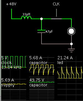
Just in case this is relevant...

Here is an example of pulse smoothing, using choke and capacitor.

The component values are chosen for a 20 kHz operating frequency, and pulses in the area of 10A through an led.

As a result, smooth DC flows through the supply wires.

4805654500_1412093368.png
 
  • Like
Reactions: treez

    T

    Points: 2
    Helpful Answer Positive Rating
Noise generators produce Egress and Noise Receivers get Ingress.

To reduce egress, common mode noise can be reduced significantly with high permeability clamp-on chokes , just like all VGA video cables.

This can also work for ingress.

Heavy braid ground wire can reduce ground loss using common grounds and Litz wire reduces the inductance and eddy current loss as well.

Unless you take accurate differential voltage measurements for us to see. To accurately capture the noise , you Must use a differential merhod such as using two identical scope probes with identical short leads and twist both probe cables together.

Then you can measure noise with a DSO in storage mode for 1sec using null data on Rx/Gnd over the noise bandwidth and compare with sending data. From this I can estimate your bit error rate or BER.

If you cannot reduce the noise, then you must use a differential tranceiver.
 
  • Like
Reactions: treez

    T

    Points: 2
    Helpful Answer Positive Rating
Status
Not open for further replies.

Similar threads

Part and Inventory Search

Welcome to EDABoard.com

Sponsor

Back
Top