Continue to Site

Welcome to EDAboard.com

Welcome to our site! EDAboard.com is an international Electronics Discussion Forum focused on EDA software, circuits, schematics, books, theory, papers, asic, pld, 8051, DSP, Network, RF, Analog Design, PCB, Service Manuals... and a whole lot more! To participate you need to register. Registration is free. Click here to register now.

[SOLVED] PSS & Pnoise simulation for sample and hold circuit

Status
Not open for further replies.

je01911

Junior Member level 1
Joined
Jun 16, 2009
Messages
16
Helped
0
Reputation
0
Reaction score
0
Trophy points
1,281
Activity points
1,390
Hi guys

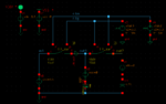
I am trying to simulate the PSS & Pnoise of simple sample and for circuit for thermal noise simulation.

sch.png

The clock signal for gate voltage swings from 0 to 2.4V (for rail to rail sampling)

The input source (PORT0) generates sine signal from 0 to 1.2V

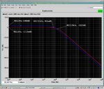
Accoring to kT/C noise theory, I expect to noise power as much as 37.692nV²/Hz because of 100fF load capacitance.

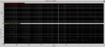
However, the simulation results shows just 0.3464fV²/Hz at flat zone (white noise by thermal) like

sim.png

I can't understand why the value computed by theory is different with simulation results in aspect of thermal noise.

If you knows the reason, please help me.
 

Attachments

  • hoge.jpg
    hoge.jpg
    236.5 KB · Views: 196
Last edited:
Thank you for your reply!

However, I have some question.

The mean of "Integrate regarding frequency" is like this?

aa.png

However, In my case, the integrated noise power is changed according to range of integration.

First, in my opinion, the integrated noise power is limited at some frequency because of low pass filter of switch and load capacitor. However, the integrated noise power is increased constantly. Is it right?

Second, if it is right, How much I should set the range of frequency when I integrate the noise ?
 

Hi je01911,

I tried to measure kT/C noise in the circuit you provided but got strange results and it did not converge.
I have attached a simple low pass filter, where we have two switches and a capacitor. The clock frequency is 10Mhz so the equivalent resistance should be approx 1Mohm with a 100fF cap. With a 1pF cap the pole should be at aprox 160kHz. I used complementary switches and non overlapping clock signals.

ktC_tb.pngktC_sim_res.png

The noise is aprox 20nV/sqrt(Hz) so it is close to the theoretical calculation.
Hope this helps.

BR Jerry
 

Attachments

  • ktC_sim_res.png
    ktC_sim_res.png
    18.3 KB · Views: 149
  • ktC_tb.png
    ktC_tb.png
    15 KB · Views: 168
Status
Not open for further replies.

Similar threads

Part and Inventory Search

Welcome to EDABoard.com

Sponsor

Back
Top