Continue to Site

Welcome to EDAboard.com

Welcome to our site! EDAboard.com is an international Electronics Discussion Forum focused on EDA software, circuits, schematics, books, theory, papers, asic, pld, 8051, DSP, Network, RF, Analog Design, PCB, Service Manuals... and a whole lot more! To participate you need to register. Registration is free. Click here to register now.

[Moved] Microchip ID on led lights

Status
Not open for further replies.

clancaster23

Newbie level 3
Joined
Sep 22, 2014
Messages
3
Helped
0
Reputation
0
Reaction score
0
Trophy points
1
Activity points
30
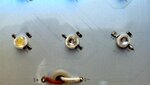
Not sure this is where to post this as I am no electrician or know much about this stuff. I have a set of led lights that I use to light my aquarium with. Each led on the board has a small chip next to it which say "201" on them. The light has 40 leds and the whole board is split in half so 20 are on one switch and 20 on the other. I noticed that one half was not lighting but I would get an occasional pulse out of them when turning the switch off and on. I got a closer look to see which light was not coming on and saw that one lights small microchip looks to be fried. There is also a white spot on this one chip that is not on any others. Now I am trying to figure out if it's something that I can replace. I'd have to identify what kind of chip it is and see if I can get one and replace it or is this whole thing basically done. Is anyone able to identify what this chip is and if I'm able to get another one and if so, how are they replaced?
 

Attachments

  • IMG_20140921_210941_370.jpg
    IMG_20140921_210941_370.jpg
    2.3 MB · Views: 56

It looks fried!

The part is a 200 Ohm SMD resistor. They cost almost nothing and are easy to purchase but because of their low cost you might find they are only sold in multiples of 10 or 100. They come in different sizes and its difficult to tell which it is from a photograph but I would guess it is size 0603. I warn you that you might find it difficult to solder a new one in place, it looks like the board may be metal backed to dissipate the heat from the components and it will drain the heat from a soldering iron just as easily. They are typically manufactued in ovens that heat the whole board to soldering temperature and trying to heat just one part of it may be tricky.

Brian.
 

In your photo I see LEDs that produce different colors.
The one with the yellow phosphor is a blue LED with a yellow phosphor that produces white light.
The clear LEDs might produce red, green or blue light.

If only one 201 resistor is fried then only its associated LED would not light, not the entire group of 20 LEDs in the half.
Since the bad half of LEDs is intermittent when the switch is activated then maybe there is a loose wire at the switch?
 

But I have determined that it is not the switch by trying to light the other half of the lights with this same switch and they work fine. It's something from the wire that goes to the board (you can see on the bottom of the picture the wire that sends power to the board) and through the board that is the problem.
 

How many LEDs are intermittent? All 20 on one side or just the single LED with a different looking resistor?

Are the two wires in your photo the only wires going to the board? Is one of those wires connected to the single switch?

How and where did you connect the switch to the LEDs on one side of the board?
 

It's the whole string of LEDs (half the lights, 20). The two wires in the picture are actually for the other string of lights. The one for this problem string is at the top of the board. So four wires all together, a black and a white for each string.

Not sure what you're asking in the third question. This isn't a DIY setup so I didn't exactly put them in.
 

The string of 20 LEDs at the top of the board are intermittent so it has nothing to do with one resistor that looks a little different (fried?) than the others.
This string has its own two wires to power it and the other string of 20 also has its own two wires to power it. Do these pairs of wires connect together and connect to the switch and to the power supply?

One of the two wires that power the intermittent 20 LEDs is broken or has a poor solder joint.
 

Some LED panels use distributed series resistors to spread the heat evenly around the board. If that's what is done here, one resistor could disable all or a large part of the board. The value of 200 Ohms does seem rather high (although not impossible) if it is a series path and there are several of them in the chain.

Clancaster23, do you know what voltage is fed to the board? The answer will give some clues about how the LEDs and resistors are connected together.

Brian.
 

Status
Not open for further replies.

Similar threads

Part and Inventory Search

Welcome to EDABoard.com

Sponsor

Back
Top