Continue to Site

Welcome to EDAboard.com

Welcome to our site! EDAboard.com is an international Electronics Discussion Forum focused on EDA software, circuits, schematics, books, theory, papers, asic, pld, 8051, DSP, Network, RF, Analog Design, PCB, Service Manuals... and a whole lot more! To participate you need to register. Registration is free. Click here to register now.

Oregon weatherstation wireless sensors

Status
Not open for further replies.

Veketti

Full Member level 3
Joined
Sep 14, 2014
Messages
164
Helped
0
Reputation
0
Reaction score
0
Trophy points
16
Activity points
1,700
Dear All,

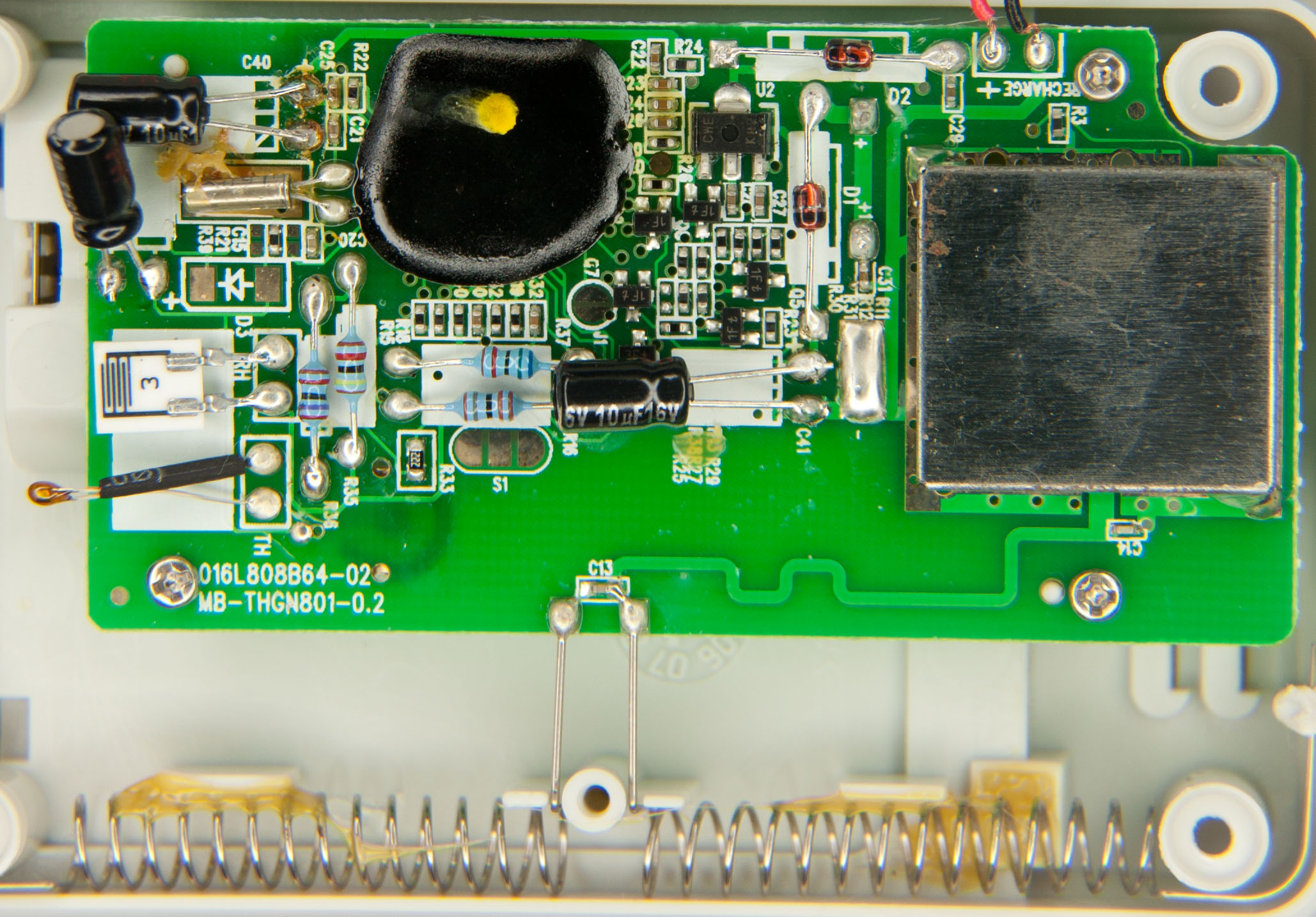
I have Oregon WMR200 wireless weather station which has three different kind of wireless sensors. Problem is that these sensors will stop intermittenly communicating with the main unit after say two ears. This is very annoying and I've tried to fix these by myself. So far I've done the obvious which is change the caps. But this doesn't seem to help. Could someone point me to right direction what should I check on this? I've got scope and multimeter on hand. So far I've had two units (wind speed/direction sensor and temperature/humidity sensor) intermittenly losing connection to the main unit. Probably same component is always failing.
Here's the picture of the PCB.

oregon.jpg

I'd be very happy if you could help me to fix this so that I wouldn't need to buy new sensor every two years..
 
Last edited by a moderator:

I'm not able to edit original post so I'll reply to add more images.
Here's more accurate image of the PCB

And this is what's inside of the metal casing:
 

Anyone? Could it be that HD R433M filter resonator which could be getting weaker, if that is the component which is responsible of the radio communication? No idea, just guessing. Hope somebody could help..
 

Do you see any sign that the circuit boards corroded from exposure to the elements? Examine carefully with a magnifying glass. Can you see crust, and/ or damage to traces?

What about batteries? When their voltage declines, it might cause deterioration within IC's, because of inability to reach proper operation.

Just brainstorming. Don't know for sure.
 
Traces are all like new. They do have intact protective layer. Nothing you can visually see that could be wrong there. Not the batteries either, as I've changed them.
 

Of course there is an easy answer which you already thought of. A weak batch of a particular component. Substandard electronic parts are becoming increasingly common. It would explain why you had several units go bad the same way.

The transmitter section is the obvious suspect. There is a transistor under the metal shield. If you could take volt measurements at its terminals, at the moment it is transmitting, that might give you an idea whether it is amplifying. This won't be easy, because if it's like my wireless temperature sensor, it only sends once every few minutes.

An alternative is to desolder the transistor, and test it.
However to desolder it without ruining it... That won't be easy.

Another alternative is to construct your own transmitter. You'd need to find where the coded message goes to the present transmitter. That looks like a crystal under the metal shield. You'd need to work that into your transmitter too.
 
Better way is to compare two units in the area that fails. I guess display works.

Tx is 433 MHx , Rx is 60KHz for WWVB if in USA for clock sync.

call Oregon Scientific for service on both units.

my handheld OS unit is over 10yrs and still ticks but no radio inside.
 
I presume you are using the sensor outdoor, it has to stand harsh temperature conditions. I doubt that you can locate the defective part by visual inspection.

A possibly weak part is the COB (chip on board).
 
Alright Gents, did some measuring as BradtheRad suggested. That transistor under the shield seems to be PNP transistor with printing "YK-" and measured following: When transmitting it seems to output square wave of 1kHz and amplitude 0.96ms 50% duty cycle. Lower left pin (emitter?) -3.11V low and -2.68V high. Top left pin (collector?) -3V low and -1.98V high. Right mid pin (base?) does read +3.136V and drops 3.01V when transmitting. Does this sound about right? I'm sorry I have no idea what values should it read and I didn't find any datasheets either for this.

Also measured by multimeter diode function and it reads E-B 0.795V, C-B 0.65V and C-B 405kohm. I'm not sure can you trust these as transistor is not separated from the board.. Here's the screenshot of top pin oscilloscope readout:
YK-.jpg

FvM do you mean by COB the circuit under that black substance?

Thanks all for your kind help. It's been very rewarding and educational experience.
 

Looks like the controller is still working and a problem in the transmitter exist. What you see is only the modulation waveform, your oscilloscope is most likely unable to detect the RF (915 MHz?).

But there should be some pattern in the 1 kHz signal, not just 50% duty cyle continuously during transmission.
 
Do you mean that the transistor is working as it should in amplifying the signal?

Actually now that you said, I zoomed that 1kHz signal and there is indeed pattern there (20mV peak). Is this the message that it's sending?
peak.jpg

According to brochure this works in 433mHz, where did that 915mHz came from?
 

Yes, that looks like coded information. Similar to signals put out by a tv remote control.

Have you placed the two units close together, to see if the receiver will pick up broadcasts, even if they are weaker than normal?
 
Yes it can communicate with the main unit, but intermittenly it drops out and that might last many hours. Didn't think of that perhaps it's useless to troubleshoot it if the issue is not on at the moment as it's intermittent. Gets too complicated. However I could for fun change some components to see if it helps. But it seems eg. that transistor is not easy to find anywhere. Umm, or I'll just dump it and next time buy Davis when next sensor give up.. :)
 

Yes, intermittent problems are toughest to solve.

1.

You get a differential of a few volts at the transistor. This suggests it is not shorted internally.

2.

One reason for an unreliable transmitter, is that oscillations are not always able to start, or, if they start, they contain harmonics.

433 MHz seems to be the correct frequency which your transmitter should be on. If it contains 915, that will scramble things.

3.

It looks as though there is no component at C8. I wonder if the boss said 'Leave it out, since the unit will still work a few years without it'? Perhaps installing a small capacitor at C8 will restore reliable operation?
 
Good idea to try that C8. At least I've got nothing to lose. I soldered there 100pf ceramic capacitor and it stop communicating with the main unit. It was pretty tricky as the pads are very tiny so I might have shorted something or could it be that 100pf is too high/small value?
 

Good idea to try that C8. At least I've got nothing to lose. I soldered there 100pf ceramic capacitor and it stop communicating with the main unit. It was pretty tricky as the pads are very tiny so I might have shorted something or could it be that 100pf is too high/small value?

It was just something to try. I don't know if 100 pF was low or high.

Since it doesn't help, you may as well remove it.

Intermittent transmitter, on more than one unit. Suppose it is hot/cold related? Try a hot air blower on certain areas. Alternatively, a freeze spray.
 
Status
Not open for further replies.

Part and Inventory Search

Welcome to EDABoard.com

Sponsor

Back
Top