Mithun_K_Das
Advanced Member level 3
- Joined
- Apr 24, 2010
- Messages
- 899
- Helped
- 24
- Reputation
- 48
- Reaction score
- 26
- Trophy points
- 1,318
- Location
- Dhaka, Bangladesh, Bangladesh
- Activity points
- 8,253
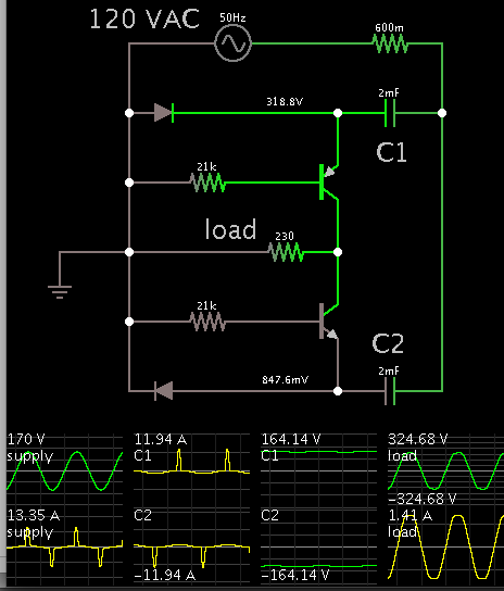
I've been looking for transformer-less AC-AC converter. How these converters works, what is the working mechanism and everything.
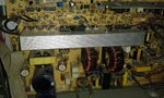
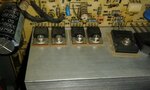
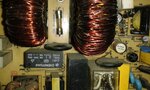
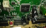
I found a voltage stabilizer that is working very fine, that circuit is using just a big inductor and few FETs. I still don't know what is the technology behind this.
Need help. Thank in advance.
I found a voltage stabilizer that is working very fine, that circuit is using just a big inductor and few FETs. I still don't know what is the technology behind this.
Need help. Thank in advance.