Continue to Site

Welcome to EDAboard.com

Welcome to our site! EDAboard.com is an international Electronics Discussion Forum focused on EDA software, circuits, schematics, books, theory, papers, asic, pld, 8051, DSP, Network, RF, Analog Design, PCB, Service Manuals... and a whole lot more! To participate you need to register. Registration is free. Click here to register now.

ir leds flickering problem

Status
Not open for further replies.

shyckh

Newbie level 5
Joined
Feb 3, 2013
Messages
8
Helped
0
Reputation
0
Reaction score
0
Trophy points
1,281
Activity points
1,338
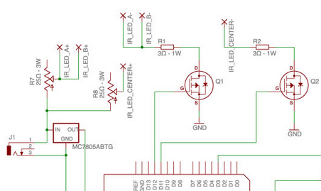
i am working on a project for which i need two set of ir leds to flicker alternatively with respect to each other with the same input frequency. the input signal is coming from the vsync of ps3eye camera. i have given the the vsyn signal to 555 timer. the output of 555 timer is being given to arduino board pin3 as an interrupt. the remaing circuit is attached. the problem i am facing is that leds would not turn off completely rather thay just dims. i want leds to be completely off if one set of leds is on. any help on it would be appreciated. also i want to know what is the frequency of v sync signal?

3235573200_1410713895.png
 

Two possibilities:

* Your mosfet icons appear unconventional, because they contain an internal diode which points downward instead of upward. In such a case the mosfets will always conduct.

* The gate should be pulled to 0V, in order to turn off the mosfet. However if pins D11-12 go to high impedance, the gate adopts an unknown voltage. It may be exposed to magnetic fields (including mains hum). The mosfets may then turn on and off.

It helps if you connect a 10k resistor between gate and source.
 

You are shown a P Ch FET for a low side switch which should be an N ch enh. mode MOSFET.

THe RdsOn must be lower than that of the LED. (<1 ohm) depending on p/n
Since your input voltage is too high ( >7V, your could actually use 2 or 3 LED's in series to get more power out then use smaller R's

What is the point of alternating IR light, if the frame rate is 60Hz? You would be better off with steady light and use 10Watts of IR LEDs in a array running off DC, than pulsing it. The only power you might save is during Vsync blank.
 

Two possibilities:

* Your mosfet icons appear unconventional, because they contain an internal diode which points downward instead of upward. In such a case the mosfets will always conduct.

* The gate should be pulled to 0V, in order to turn off the mosfet. However if pins D11-12 go to high impedance, the gate adopts an unknown voltage. It may be exposed to magnetic fields (including mains hum). The mosfets may then turn on and off.

It helps if you connect a 10k resistor between gate and source.

Its an n-channel mosfet irf 530. i have 16 leds in each pair. 4 leds in series which are connected parallel to other 4 leds in series and so on. it will turn on all the time but when a pulse is applied on the gate it starts flickering. if i view them in camera and take picture simultaneously. it shows me that ir leds are not turning off completely rather they just dims. i will attached a 10k Pulll down resistor and see what happen... thanks for your reply sir

- - - Updated - - -

yes mosfet always conduct. when it is gated the leds start flickering. i have a load of about 16 ir leds in each pair. i should try 10k pull down resistor and will inform you about the resultl. thanks for replying. but don't you think 10K is quite a large value for a mosfet. correct me if i am wrong that 10K resistor rule is only applied to transistors not on fets.

- - - Updated - - -

it remain conducting untill gated. don't you think 10k is a large value for mosfet.
Two possibilities:

* Your mosfet icons appear unconventional, because they contain an internal diode which points downward instead of upward. In such a case the mosfets will always conduct.

* The gate should be pulled to 0V, in order to turn off the mosfet. However if pins D11-12 go to high impedance, the gate adopts an unknown voltage. It may be exposed to magnetic fields (including mains hum). The mosfets may then turn on and off.

It helps if you connect a 10k resistor between gate and source.

- - - Updated - - -

i am using it so that i can track the motion of eyes using reflection image of ir leds in eyes. so that i need high frequency.
 

by applying 10K resistor one set of leds starts turning on and off while on other set there is no effect. the arduino sketch is :

Code:
[syntax=dot]
/*

 
 The strobe (also called vertical sync) from a camera is broken out and
 drives an interrupt on pin 3 (interrupt 1). The loop() uses the offset
 defined by vsync() to determine whether the LEDs on pin 11 or the LEDs
 on pin 12 should be on.
*/

/*
 This should be set to the same fps you expect the camera to capture at.
*/
const float fps = 30;

/*
 If you are using a PS3Eye or other rolling shutter camera, you also
 need to set the exposure. An exposure value of 1 means the camera is
 exposing half the sensor at any given moment, and an exposure value of
 0 means the sensor is exposing only one row at any given moment.
*/
const float exposure = 1;

/*
 For nicer cameras with global shutters, define USE_GLOBAL_SHUTTER.
 This will disable the use of the exposure variable, and leave the LEDs
 on as long as possible.
*/
//#define USE_GLOBAL_SHUTTER

/*
 Most cameras have a strobe signal that is tied to HIGH, and brought to
 LOW when a frame is captured. If you are buffering the signal with a
 transistor, this will invert the behavior and the polarity of the change
 will probably be RISING. If you are tapping the strobe directly, the
 polarity will probably be FALLING.
*/
const int polarity = RISING;

/*
 Feel free to use different LED output pins.
*/
const int glintPin = 11;
const int pupilPin = 12;

/*
 The rest of the code shouldn't change between setups.
*/
const int interrupt = 1;
volatile unsigned long offset = 0; 
volatile boolean firstFrame = true;
const float microScale = 1000000;
const float totalTime = microScale / fps;
const float cutoff = 1 - (exposure / 2);

float position;

void setup() {
 pinMode(pupilPin, OUTPUT);
 pinMode(glintPin, OUTPUT);
 attachInterrupt(interrupt, vsync, polarity);
}

void loop() {
 position = (float) (micros() - offset) / totalTime;
 #ifdef USE_GLOBAL_SHUTTER
  if(position < 1) {
   digitalWrite(pupilPin, HIGH);
   digitalWrite(glintPin, LOW);
 } else {
   digitalWrite(pupilPin, LOW);
   digitalWrite(glintPin, HIGH);
 }
 #else
 if(position < cutoff) {
   digitalWrite(pupilPin, HIGH);
   digitalWrite(glintPin, LOW);
 } else if (position > 1 && position - 1 < cutoff) {
   digitalWrite(pupilPin, LOW);
   digitalWrite(glintPin, HIGH);
 } else {
   digitalWrite(pupilPin, LOW);
   digitalWrite(glintPin, LOW);
 }
 #endif
}

void vsync() {
 firstFrame = !firstFrame;
 if(firstFrame)
   offset = micros();
}[/syntax][code]

the out put of 555 timer has a pulse width of 16.6 ms
 

Status
Not open for further replies.

Part and Inventory Search

Welcome to EDABoard.com

Sponsor

Back
Top