amartin32
Newbie level 4
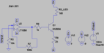
I (Novist) am currently building a analog circuit that consists of an LT 1056 op amp and NPN 2n2304 transistor. The objective is to vary the amount of current flowing through the LED (the 148 ohm resistor) proportionally to the input signal.
I have done this successfully with this circuit however now I would like to use this for input signals in the high kHz range to the low MHz range. The problem I have seen so far is the breadboard I used had a lot of parasitic capacitance and the 741 Op Amp how too low of a slew rate. Now that I everything seems find except when I go to 10kHz with a signal generator to oscilloscope. I see a phase shift on the output and a reduction in amplitude.
I think this could be due the Miller Effect? Their may be some stray capacitance at the junction of the transistors?
I computed the BJT load line for the operation of the NPN transistor and it shows we are operating in the linear region. (I was getting cut off before)
I appreciate any feedback as to find out why I get the amplitude reduction, phase shift and you have any design suggestion.
THANKS!