Continue to Site

Welcome to EDAboard.com

Welcome to our site! EDAboard.com is an international Electronics Discussion Forum focused on EDA software, circuits, schematics, books, theory, papers, asic, pld, 8051, DSP, Network, RF, Analog Design, PCB, Service Manuals... and a whole lot more! To participate you need to register. Registration is free. Click here to register now.

Need help regarding generating 60hz frequency using 50hz mains

Status
Not open for further replies.

khaja_minhaj

Junior Member level 3
Joined
Sep 22, 2011
Messages
27
Helped
0
Reputation
0
Reaction score
0
Trophy points
1,281
Activity points
1,474
Hi!
I need to convert incoming 230V ac 50hz frequency to 60hz with same voltage. The output has a amps rating of 36A.
My idea is to step down 230v to 12 v and digitalize using a diode and make it to 5v using resistor
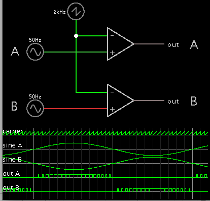
network. This is fed to the microcontroller's gpio pin and the microcontroller can be used to generate pwm pulses according to the frequency of the incoming signal. then using IGBTs to convert it to AC signal. The microcontroller gives its output through two GPIOs. I have seen this on a website Romanblack.com
My main doubt is, how am I going to calculate and divide PWM pulses time interval for a 60hz frequency?

Thanks
 

Not quite sure what you've gotten yourself into here. You are talking about making an 8 KILOWATT frequency converter. Why do you need to divide the incoming frequency? You need to produce 60Hz, so just produce 60 Hz. The input frequency is pretty much irrelevant.

The way this is normally done is you convert your input power to DC, and then chop (PWM) that to get your AC output. Thus, the input frequency doesn't matter, since you're converting it to DC.
 
  • Like
Reactions: FvM

    FvM

    Points: 2
    Helpful Answer Positive Rating
Hi barry!
You are right. I have decided to produce pwm signal with 60hz frequency without regard to input frequency. But my doubt is do I really need microcontroller to produce sine wave or is it possible with SG3525 IC also?

Actually I need to design this converter for a user who wants to increase the speed of his motor by increasing the frequency.

Thanks
 

The SG3525 is PWM controller, it has nothing to do with sinewaves unless your input is a sinewave. Basically, the width of your pulse is proportional to your input. You will need some source of a sinewave, whether it's a microprocessor or an analog oscillator that drives your PWM circuit.
 

My main doubt is, how am I going to calculate and divide PWM pulses time interval for a 60hz frequency

For this part of your question, here is one analog method:

8835572900_1410960322.png
 

Hi!
I am trying to generate PWM from 8051 microcontroller of high frequency (20khz) so that I can give this to H bridgr driver . There is one output from microcontroller and anotther one is the inverted of the previous one. When I check the ouput of the H bridge using oscilloscope, a sawtooth is appearing instead of continous sine wave.
I am not sure where I am going wrong. Please anybody can help?
I am using Timer 0

Here is my code.


Code dot - [expand]
1
2
3
4
5
6
7
8
9
10
11
12
13
14
15
16
17
18
19
20
21
22
23
24
25
26
27
28
29
30
31
32
33
34
35
36
37
38
39
40
41
42
43
44
45
46
47
48
#include<REG52.H>
 
#include <stdio.h>    
 
 
     sbit PWMPIN1=P2^7;
         sbit PWMPIN2=P2^5;
    unsigned char pwm_width;
    bit pwm_flag = 0;
    
void pwm_setup();
 
void timer0() interrupt 1 {
    if(!pwm_flag) { //Start of High level
    pwm_flag = 1;   //Set flag
    PWMPIN1 = 1;    //Set PWM o/p pin
        PWMPIN2 = 0;    
    TH0 = pwm_width;    //Load timer
    TF0 = 0;    //Clear interrupt flag
    return; //Return
    }
    else {  //Start of Low level
    pwm_flag = 0;   //Clear flag
    PWMPIN1 = 0;    //Clear PWM o/p pin
        PWMPIN2 = 1;    
    TH0 = 255 - pwm_width;  //Load timer
    TF0 = 0;    //Clear Interrupt flag
    return; //return
    }
    }
 
         void main()
         {
             pwm_setup();
             while(1)
             {
             }
         }


    void pwm_setup(){
    TMOD = 0;
    pwm_width = 128;
    EA = 1;
    ET0 = 1;
    TR0 = 1;
    }

 
Last edited by a moderator:

Hi,

what you want to build is an inverter for motor applications.
There are lots cheaply to buy. Does it really makes sense to build yourown?

Actually I need to design this converter for a user who wants to increase the speed of his motor by increasing the frequency.

This is usually true for three phase motors (or steppers or BLDC) but not for usual 1phase AC motors.

Klaus
 

Hi,

what you want to build is an inverter for motor applications.
There are lots cheaply to buy. Does it really makes sense to build yourown?


This is usually true for three phase motors (or steppers or BLDC) but not for usual 1phase AC motors.

Klaus


No. My main intention is not to build an inverter, but it is a frequency converter and it steps up the load to 4 A or 10 A as required.

Firstly, I must build an inverter that converts DC to AC and then I can set the frequency.
Hope you understand my objective.
 

Hi,

where do you see the difference to a ready to buy inverter?

Klaus
 

Hi!
I am trying to generate PWM from 8051 microcontroller of high frequency (20khz) so that I can give this to H bridgr driver . There is one output from microcontroller and anotther one is the inverted of the previous one. When I check the ouput of the H bridge using oscilloscope, a sawtooth is appearing instead of continous sine wave.
I am not sure where I am going wrong. Please anybody can help?
I am using Timer 0

Then you need frequency variable inverter for that you written some code and checking output in H bridge.

First make sure the PWM ouput from the controller is similar to the one #5 OUT A and OUT B
Actualy saying you will need two pwm outputs or a logic to make a two pwm outputs then only your H bridge will work.
It is not advisable to test the output in H bridge unless you are confident in MC output.

So now tell what is your controller output and what is the problem.
 

I check the ouput of the H bridge using oscilloscope, a sawtooth is appearing instead of continous sine

You are loading TH0 with the pwm_width content, however any change are done at this variable on code above. You must perform an access to a table containing already calculated values for a sine and store it to that variable.
 

Hi Venkadesh!
As I said, I am generating 2 PWM outputs each of which is inverted of other. I checked in the oscilloscope the outputs of pwm signal, they are OK(with 50% of duty cycle). The output at H bridge is of random signal and not sinewave.
 

Connect the two pwm signals in CRO and post the images here..

Is that #6 code you are using? Its not at all PWM, its just a square wave.

You are using timer to generate wave form, Do you any have inbuilt PWM module in your controller?
You have to use sine function or sine table in your program otherwise you cannot get sine wave.
 

Hi!
The 2 outputs are not pwm and they are fixed frequency pulses but inverted. I have posted the image of output. I changed the pwm_width to 80.

3231989800_1411724552.jpg


You could be right as said by andre_teprom that I should call the values from a sine table. I will try this out and post the results.

Thanks for the support
 

Hi!
The microcontroller I am using here is 89S52 which does not have builtin PWM module. So how should I generate pwm signal from the sine table?
I have got the sine table but how to assign values to the timer when there is no pwm pin?

Please suggest.

Here is my code:
Code:
#include<REG52.H>
#include <math.h>
#include <stdio.h> 

void InitSinTable();
void pwm_setup();

 sbit PWMPIN1=P2^0;
 sbit PWMPIN2=P2^1;
 
// unsigned char pwm_width;
 unsigned char sample=0;
unsigned char wave[];
 bit pwm_flag = 0;
/*
unsigned char code wave[]=
{
0x80, 0x83, 0x86, 0x89, 0x8C, 0x90, 0x93, 0x96,

0x99, 0x9C, 0x9F, 0xA2, 0xA5, 0xA8, 0xAB, 0xAE,

0xB1, 0xB3, 0xB6, 0xB9, 0xBC, 0xBF, 0xC1, 0xC4,

0xC7, 0xC9, 0xCC, 0xCE, 0xD1, 0xD3, 0xD5, 0xD8,

0xDA, 0xDC, 0xDE, 0xE0, 0xE2, 0xE4, 0xE6, 0xE8,

0xEA, 0xEB, 0xED, 0xEF, 0xF0, 0xF1, 0xF3, 0xF4,

0xF5, 0xF6, 0xF8, 0xF9, 0xFA, 0xFA, 0xFB, 0xFC,

0xFD, 0xFD, 0xFE, 0xFE, 0xFE, 0xFF, 0xFF, 0xFF,

0xFF, 0xFF, 0xFF, 0xFF, 0xFE, 0xFE, 0xFE, 0xFD,

0xFD, 0xFC, 0xFB, 0xFA, 0xFA, 0xF9, 0xF8, 0xF6,

0xF5, 0xF4, 0xF3, 0xF1, 0xF0, 0xEF, 0xED, 0xEB,

0xEA, 0xE8, 0xE6, 0xE4, 0xE2, 0xE0, 0xDE, 0xDC,

0xDA, 0xD8, 0xD5, 0xD3, 0xD1, 0xCE, 0xCC, 0xC9,

0xC7, 0xC4, 0xC1, 0xBF, 0xBC, 0xB9, 0xB6, 0xB3,

0xB1, 0xAE, 0xAB, 0xA8, 0xA5, 0xA2, 0x9F, 0x9C,


0x99, 0x96, 0x93, 0x90, 0x8C, 0x89, 0x86, 0x83,

0x80, 0x7D, 0x7A, 0x77, 0x74, 0x70, 0x6D, 0x6A,

0x67, 0x64, 0x61, 0x5E, 0x5B, 0x58, 0x55, 0x52,


0x4F, 0x4D, 0x4A, 0x47, 0x44, 0x41, 0x3F, 0x3C,

0x39, 0x37, 0x34, 0x32, 0x2F, 0x2D, 0x2B, 0x28,

0x26, 0x24, 0x22, 0x20, 0x1E, 0x1C, 0x1A, 0x18,

0x16, 0x15, 0x13, 0x11, 0x10, 0x0F, 0x0D, 0x0C,

0x0B, 0x0A, 0x08, 0x07, 0x06, 0x06, 0x05, 0x04,

0x03, 0x03, 0x02, 0x02, 0x02, 0x01, 0x01, 0x01,

0x01, 0x01, 0x01, 0x01, 0x02, 0x02, 0x02, 0x03,

0x03, 0x04, 0x05, 0x06, 0x06, 0x07, 0x08, 0x0A,

0x0B, 0x0C, 0x0D, 0x0F, 0x10, 0x11, 0x13, 0x15,

0x16, 0x18, 0x1A, 0x1C, 0x1E, 0x20, 0x22, 0x24,

0x26, 0x28, 0x2B, 0x2D, 0x2F, 0x32, 0x34, 0x37,

0x39, 0x3C, 0x3F, 0x41, 0x44, 0x47, 0x4A, 0x4D,

0x4F, 0x52, 0x55, 0x58, 0x5B, 0x5E, 0x61, 0x64,

0x67, 0x6A, 0x6D, 0x70, 0x74, 0x77, 0x7A, 0x7D

};*/

void timer0() interrupt 1 
	{
    
	  TH0 = wave[sample];
		
    sample++;

    if( sample >= 255 )
    sample = 0;
         if(sample==sample+64)
				pwm_flag=~pwm_flag;
    if(TH0==255)
		TH0=0;
    TF0 = 0;	//Clear interrupt flag
    return;	//Return
   
    }

 void main()
		 {
			 pwm_setup();
			 
			 while(1)
			 {
				 InitSinTable();
				  if(pwm_flag)
					{
						PWMPIN1 = 1;	//Set PWM o/p pin
		        PWMPIN2 = 0;
					}
					else
					{
						PWMPIN1 = 0;	//Set PWM o/p pin
		        PWMPIN2 = 1;
					}
			 }
		 }


    void pwm_setup(){
    TMOD = 0;
//    pwm_width = 128;
    EA = 1;
    ET0 = 1;
    TR0 = 1;
    }
	
	
void InitSinTable()
{
//sin period is 2*Pi

const float step = (2*3.14)/(float)256;

float s;

float zero = 128.0;
int i;

//in radians

for( i=0;i<256;i++)
{

s = sin( i * step );

//calculate OCR value (in range 0-255, timer0 is 8 bit)

wave[i] = (unsigned ) ceil(zero + (s*127.0));
	
}
}


Code C - [expand]
1
2
3
4
5
6
7
8
9
10
11
12
13
14
15
16
17
18
19
20
21
22
23
24
25
26
27
28
29
30
31
32
33
34
35
36
37
38
39
40
41
42
43
44
45
46
47
48
49
50
51
52
53
54
55
56
57
58
59
60
61
62
63
64
65
66
67
68
69
70
71
72
73
74
75
76
77
78
79
80
81
82
83
84
85
86
87
88
89
90
91
92
93
94
95
96
97
98
99
100
#include <REG52.H>
 
void pwm_setup(unsigned char);
 
sbit PWMPIN1=P2^0;
sbit PWMPIN2=P2^1;
 
#define HALF_SINE_TABLE_SIZE 128
#define MAX_SINE_VALUE         0xFF
#define TIMER_CLK_FREQ       1000000
 
unsigned int  Timer_Peiod;
 
const unsigned short sine_table[HALF_SINE_TABLE_SIZE]= {\
0x80, 0x83, 0x86, 0x89, 0x8C, 0x90, 0x93, 0x96, 0x99, 0x9C, 0x9F, 0xA2, 0xA5, 0xA8, 0xAB, 0xAE,\
0xB1, 0xB3, 0xB6, 0xB9, 0xBC, 0xBF, 0xC1, 0xC4, 0xC7, 0xC9, 0xCC, 0xCE, 0xD1, 0xD3, 0xD5, 0xD8,\
0xDA, 0xDC, 0xDE, 0xE0, 0xE2, 0xE4, 0xE6, 0xE8, 0xEA, 0xEB, 0xED, 0xEF, 0xF0, 0xF1, 0xF3, 0xF4,\
0xF5, 0xF6, 0xF8, 0xF9, 0xFA, 0xFA, 0xFB, 0xFC, 0xFD, 0xFD, 0xFE, 0xFE, 0xFE, 0xFF, 0xFF, 0xFF,\
0xFF, 0xFF, 0xFF, 0xFF, 0xFE, 0xFE, 0xFE, 0xFD, 0xFD, 0xFC, 0xFB, 0xFA, 0xFA, 0xF9, 0xF8, 0xF6,\
0xF5, 0xF4, 0xF3, 0xF1, 0xF0, 0xEF, 0xED, 0xEB, 0xEA, 0xE8, 0xE6, 0xE4, 0xE2, 0xE0, 0xDE, 0xDC,\
0xDA, 0xD8, 0xD5, 0xD3, 0xD1, 0xCE, 0xCC, 0xC9, 0xC7, 0xC4, 0xC1, 0xBF, 0xBC, 0xB9, 0xB6, 0xB3,\
0xB1, 0xAE, 0xAB, 0xA8, 0xA5, 0xA2, 0x9F, 0x9C, 0x99, 0x96, 0x93, 0x90, 0x8C, 0x89, 0x86, 0x83,\
}; // please change the sine table values by subtracting - 0x80 and multiplying by two 
   // because we don need negative values
   // Half the sine table is enough for generating full cycle
 
void main()
{
    io_init();
    pwm_setup(60);
    while(1);
}
         
void io_init(){
    PWMPIN1 = 0;
    PWMPIN2 = 0;
}         
 
void load_timer(unsigned int Time) {
TH0     = (Time & 0xFF00) >> 8;
TL0     = (Time & 0xFF);
}    
         
void pwm_setup(unsigned char freq){
 
    unsigned int ISR_freq;
 
    ISR_freq     = 2 * HALF_SINE_TABLE_SIZE * freq;
 
    Timer_Peiod = TIMER_CLK_FREQ / ISR_freq;
 
    load_timer(Timer_Peiod);
 
    TMOD     = 0;
    EA         = 1;
    ET0     = 1;
    TR0     = 1;
}


void timer0() interrupt 1 {
    static int sample = 0;
    static char sign_flag = 0, PWM_out_high = 0 ;
 
    TF0 = 0;
 
    if( ++sample >= HALF_SINE_TABLE_SIZE ) {
        sample = 0;
        sign_flag = !sign_flag;
    }
 
    if(PWM_out_high)
    Time_to_load = Timer_period - ( sine_table[sample] * Timer_period / MAX_SINE_VALUE );
    else
    Time_to_load = ( sine_table[sample] * Timer_period / MAX_SINE_VALUE );
    
    load_timer(Time_to_load);        
    
    if(sign_flag)
    {
        PWMPIN2 = 0;
    
        if(PWM_out_high)
            PWMPIN1 = 1;
        else
            PWMPIN1 = 0;
    }
    else
    {
        PWMPIN1 = 0;
        
        if(PWM_out_high)
            PWMPIN2 = 1;
        else
            PWMPIN2 = 0;
    }
 
    PWM_out_high != PWM_out_high;
}


Hi Venkatesh!
The code you sent does not produce any waveforms at input. They simply remain low. It was only first execution of the program that I got some long but straight sine wave like signal but not pwm at the output of microcontroller. It did not appeared again. Don't know why.

- - - Updated - - -

Hi!
Right now I am facing the problem of two MOSFETs burning too much.
Till now there had been no problem, but suddenly they started burning. The signal at their output is coming like a chopped sinewave, but the 2 of four MOSFETs burn.
Is this the right
https://obrazki.elektroda.pl/1487307700_1411888737.jpg


This is the circuit I got from Tahmids blog:
https://obrazki.elektroda.pl/7774018500_1411889599.jpg

- - - Updated - - -

Sorry. Forgot to mention that for the above output I used previously posted code for testing to check the cause of MOSFET burning.
 
Last edited by a moderator:

Thanks ALERTLINKS for support , but I need source code for 8051 microcontroller. DeepOne has used optocouplers in between ucontroller and MOSFETs. But that wont stop heating of MOSFETs I hope.
 

Thanks ALERTLINKS for support , but I need source code for 8051 microcontroller. DeepOne has used optocouplers in between ucontroller and MOSFETs. But that wont stop heating of MOSFETs I hope.

Which controller you are using post the data sheet..
 

Status
Not open for further replies.

Part and Inventory Search

Welcome to EDABoard.com

Sponsor

Back
Top