Continue to Site

Welcome to EDAboard.com

Welcome to our site! EDAboard.com is an international Electronics Discussion Forum focused on EDA software, circuits, schematics, books, theory, papers, asic, pld, 8051, DSP, Network, RF, Analog Design, PCB, Service Manuals... and a whole lot more! To participate you need to register. Registration is free. Click here to register now.

Transistor Saturation current confusing

Status
Not open for further replies.

4EverYoungs.71

Junior Member level 1
Joined
May 1, 2014
Messages
18
Helped
0
Reputation
0
Reaction score
0
Trophy points
1
Activity points
166
Hi everybody
I'm confused about Transistor saturation current,as i know

Vcc=Vce+Ic*RL
where
Vcc:The source voltage
Vce:Collector to emitter voltage
RL:Load Resistance

and at saturation Vce=0 Volt

my confusion is,

Is saturation current depend on the load resistance "as the equation prove" , it depends on the value of the base current or on the nature of the transistor fabrication process ?
Is the saturation current mentioned above is the same the one mentioned in the datasheet of the transistor ?
Regards.
 

Saturation is dependant on Ib and design of transistor process.
Most devices are fully saturated at only 10% of hFE or Ic/Ib=10 whichever is bigger. Some "ultra-low" Vce can saturate with Ic/Ib=50 tend to have a linear gain, hFE=500 typ.

In all cases you can interpolate the Vce voltage from Ic using the datasheet and if Rce is not given, you can derive it from the slope of V vs I in the saturation region.

Thus when acting as a switch, with a load on collector,
Vcc=Ic(Rc + rCE) where rCE is the equivalent collector-emitter resistance, similar to RdsOn on a FET.

Diodes Inc. uses this parameter in all their low Vce(sat) transistors.
**broken link removed** . ZUMT619 SOT323 has Rce(sat)=160mΩ at 1A whereas a P2N2222 is 420mΩ at 0.5Amax
 

Thanks for ur help,
as i understood from ur description that
it depends on Ib and not the load,hence
i can calculate the maximum allowed load resistance from the eq "Vcc=Ic(RL+Rc)" as for the example u've give
the maximum allowed current for P2N222 is .5A at 420 ohm so if i have a 12V dc source then the load resistance must not exceeds
12/0.5-420=-396 ohm -> it doesn't make a sense to me(negative resistance) or may i'm doing some thing wrong
pls advice
 

Hello.

Cut and saturation using BJT is really easy, it may take practise.

When your transistor is not cutted nor saturated it works as constant current source. The C-E junction vary its voltage to keep the current being constan through the load.

But if you want 1A through a 1Kohm resistor, you would have 1Kv between its terminals, which is impossible when working with 15V, 12V,9V, 5V, etc supply voltages.

When C-E voltage goes out from a value your BJT is cutted or saturated. When VCE is less than -aproximately- 0,7V your transistor is saturated, which means that current will be determined by the load value and the supply voltage, instead of the base current (IB).

When VCE is near or almost reaching +Vcc (or the entire difference between what you connect to the "output mesh", which would be the emitter and collector) your BJT is cutted.

How do you get that? Well, BJT is first teached as amplifier in the linear zone and then as 'switch' , what sometimes leads one to think it's hard to make it commute.

When your load is high and/or your base current too you are doing that.

Think about it like this: When you put a base at the current, you are asking C-E junction to let a current pass through it.
That current will be hFE times the one you put at base.

If you ask for a 1mA current, for example, your hFE is 100 (that means a 10uA through the base) and your load resistance 1K ohm, supplying with 12V the current will be 1mA. VCE voltage will vary so the voltage between your 1K load terminals is 1V. Despite that, if you put 10mA through the base (hFE=100), you are asking to let a 1A current flow through C-E, which would be impossible since your load resistance is about 1Kohm and your supply of 12V. Components are legal, they doesn't break the ohm's law, if you though the opposite.

When all that happens, your transistor will LET a 10A current flow. I mean that if your load doesn't allow such a high value, current won't be that high. It just LET it flow, but doesn't generate it because it's impossible according to ohm's law.

And what does it remind you? A switch acts like that, it LETS a current flow but doesn't keep it constant.


All that explaination was for you to understand. Let's go to mathematics.

For saturation:
- VCE<=0,2V (or check it at datasheet). It increases a bit with IC current.
- VBE>0,7V (or check it at datasheet).
- Load ALWAYS at collector (if it goes to emitter your VBE saturation voltage will increase by (IC+IB).RE being RE the emitter load).
-Be aware of negative voltages (sometimes split supply is used and B-E junction may be destroyed).

For cut:
- VCE almost (or equal) VCC (respect from emitter voltage...).
- VBE< 0,7V (or check at datasheet), B-E junction mustn't be polarised.


Well, that's some of my knowledge. Just ask if you don't understand anything.

Good luck with that.

Bruno.-
 

I looked at 3 or 4 datasheets for the 2N2222 and PN2222:
1) Their maximum collector current is 800mA.
2) Their maximum spec'd saturation current is 500mA when the base current is 50mA then the maximum saturation voltage loss is 1.6A. At this high current they over-heat quickly so they are pulsed on for only 0.3ms or less and 15ms or more pauses between pulses.

What is "420 ohms"? SunnySkyguy said the on-resistance of a PN2222 is 420mΩ at 0.5A max. 420mΩ is 0.42 ohms. The datasheet says its maximum saturation voltage loss is 1.6V at 500mA which is 3.2 ohms.
With a 12V supply, the load resistance should not be less than 12V/0.5A= 24 ohms for short duration pulses with plenty of pause time between pulses. Your transistor might have a saturation voltage loss less than its maximum of 1.6V so it will heat less. If you want it to be turned on continuously then it will be at its maximum temperature when it dissipates 400mW in 25 degrees C ambient air. Maybe its saturation voltage will be 1.3V then its maximum continuous current must be limited to 400mW/1.3V= 308mA. Then the minimum collector resistor with a 12V supply is (12V - 1.3V)/308mA= 34.7 ohms but use a higher value so that the transistor is not so hot.
 

..............................
the maximum allowed current for P2N222 is .5A at 420 ohm so if i have a 12V dc source then the load resistance must not exceeds
12/0.5-420=-396 ohm -> it doesn't make a sense to me(negative resistance) or may i'm doing some thing wrong
It's 420 milliohm not 420 ohms so the equation is 12/0.5 - .42 = 24 - .42 = 23.58Ω, which is the minimum load resistance value to keep the transistor in saturation at an Ic of 0.5A with an Ib of 50mA (not the maximum as you stated).
 

Transistor has a whole region in it's Vce-Ic characteristics called saturation region. Different Ic currents has different Vcesat voltages. You can ask what is saturation voltage at maximum allowable collector current or what is saturation voltage at Ic=50mA. Some transistor datasheet may have curve of Vcesat-Ic.

Here it is explained: https://www.electronics-tutorials.ws/transistor/tran_4.html
 

Allow me to make some corrections to my 1st comment from oversimplification...
You were correct to say Vcc=Vce+Ic*RL (since rCE<<RL). For a transistor to be a suitable "switch", you need to consider the % voltage drop and % resistance for power dissipation in I²R.

hFE=Ic/Ib is varies in the "linear" region and drops quickly towards "saturation"
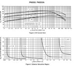
pn2222a.jpg
The Standard Test method is a pulse (see fine print)
pn2222a1.jpg
Whenever you see Tj=25'C in the spec it means tested with a pulse so Tj does not rise ( which affects the results)
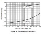
The temperature coefficent of the Vce(sat) and Vbe are both negative [mV/°C] and vary with current.
pn2222a3.jpg

The collector emitter equivalent resistance rCE=Vce(sat)/Ic depends on each device spec and whether it is typical, worst-case, pulsed or continuous, so take note.

pn2222a2.jpg
So Vce is directly controlled by Ib , while Ic is limited by Vcc/RL

The plastic version PN2222 of the 2N2222 ( which was in the metal can) , is an old "faithful" transistor but no longer the best one to use these days, but still used for educational purposes.
 

Vcesat(Ic) is not constant but it is nonlinear function. You generally can not say Vcesat=rCE*Ic because rCE is not constant but depends on IC. Different transistors has different dependancy.
Since Ic in saturation depends on Rc, Vcc and Vcesat Ib can be greater than needed for specific Ic while max allowable Ib must not be exceeded.
 

SunnySkyguy said the on-resistance at 500mA and when the base current is 50mA for the PN2222 or 2N2222 is 420mΩ and recently posted the graph showing its saturation voltage loss from its datasheet. The saturation voltage is shown as 0.21V so the on resistance is 0.21V/500mA= 420mΩ.

BUT the graph is for a "typical" transistor. You cannot buy a typical one, you get whatever they have. Maybe all the typical and better transistors were not produced in the latest production run or maybe all the "good ones" were sold. A purchased transistor might have minimum spec's with a maximum saturation voltage of 1.6V which I said, and is shown in the guaranteed spec's printed in text on its datasheet.
 

Hello for all
yes i was mistaken it's 420 m Ohm and not 420 Ohm
and thanks for your help,
I've read all ur comments in hurry,but i promise to read it once again later,and if there any thing not understood i will ask u.
Regards
 

Yes the Rce is nonlinear, but mainly at low currents, but above 1% of rated current, it is constant for the Ic/Ib ratios used in the spec.

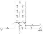
Note the collector resistor in the Gummel–Poon model below, which reduces to the simpler Ebers–Moll model
Rce2.jpg

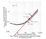
The Rce is slope of the Ic vs Vce curve below and is constant between 1% and rated current.
e.g. This is an ultra low Rce device not typical of all transistors.
RCE1.jpgRce.jpg

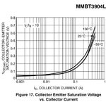
Another useful tip is that in Saturation , lowering BJT's collector/base current ratio lowers Rce resistance ( from 50:1 to 5:1 ) but this is always much lower than linear current gain hFE. Remember that the straight slope only applies to Lin-Lin or Log-Log scales and Lin-Log will be quadratic. ( so pick to points near top if curve to compute deltaV/deltaI=Rce for given Ic/Ib ratio.
(See 3904 graph below)


Meanwhile MOSFET's RdsOn reduces with increasing gate voltage above threshold.
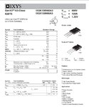
But MOSFETs have a large capacitance that can make the Gate drive current at high frequency approach that of BJT's of 10% in saturation. BJT's however , are capable of being designed for much higher Vce breakdown voltages. Hence the best of both worlds is the MOSFET gate integrated with bipolar CE is called an IGBT, best in the range of 100 ~ 1000A and 250~2000V)e.g. See IGBT spec attached.

if you don't have any more ? Then pls close as answered.
 

Attachments

  • image.jpg
    image.jpg
    382.7 KB · Views: 89
  • image.jpg
    image.jpg
    95.2 KB · Views: 421

...............................
Hence the best of both worlds is the MOSFET gate integrated with bipolar CE is called an IGBT.
Not necessarily. An IGBT must derive the base current internally, and the current basically goes through two diode drops so its saturation voltage is typically in the region of 1.5 to 2V. They work great for some high current, high voltage applications but MOSFETs or standard BJTs are better at lower currents/voltages where a low ON voltage is desired.
 

Yes IGBT may be best only for switching very high VA products from 10k to 10M! (VA). The designs are designated as 3rd, 4th, 5th ... generation types.


True, for a Saturated Switch one must decide what current,(avg,pk)or pulse, Vsat, speed, input , then cost. Each choice has a tradeoff for gain vs speed vs cost vs Rsat.

Consider a good automotive relay, the current gain from coil to contacts can be as high as 2000, but slow compared to the BJT with Ic/Ib (sat)= 10 to 50 and then the MOSFET takes almost no current as a static switch except the capacitance during threshold switching.
 

Hello.
And what does it remind you? A switch acts like that, it LETS a current flow but doesn't keep it constant.
Bruno.-

Special thanks to "BrunoARG" for its description,
but what u mean by the quoted text above?
if i had transistor as switch and the load resistance for example =5k Ohm,Beta=100 and Vcc=12V (ignore Rce)
it supposed that
at Ib=0 the transistor is in cutoff
at Ib=24 uA the transistor is fully saturated and the load get the maximum current allowed as long as the base current is fed into the base,
what's make him not keep constant


I just gave you an example. A transistor can work as a switch and as a current source.

The values you put there are correct, but take into account that you determine the IB with a resistor connected to a positive voltage. That positive voltage must be greater than 0,7V approximately.

You could connect a 240mV source to a 10K resistor and have 24uA, but you won't polarise the junction and it won't let any current pass.

When you overfeed (or properly meant, saturate) the base, your transistor will allow a higher current pass, which is limited by the load resistor, and it will determine the current instead of the base current.

I'll give another example: If you have a hose with your finger at its tip, and you open the tap, you will control the water current through it. If you gradually let more water pass, somewhen you will see that its amount will be limited by the tap you opened. If you open it at all, you could stop the water flow, but you will not be able to generate a infinite water current, because the load (tap) will be limiting it.

At more IB more 'water' would flow. Without it (totally blocking the hose) there will be no water flowing. Now, Without blocking the hose tip (a very high IB) the water current will not be inifinite or as high, but one determined by the tap (Load resistance).

Hope you understand.

Bruno.-
 

BrunoARG is wrong!
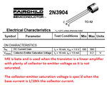
A beta of 100 is used when the transistor is a linear amplifier, not as a saturated switch. The datasheet for most little transistors show its maximum saturation voltage when the base current is 1/10th the collector current regardless of its linear beta. Then when the collector load is 5k and the supply is 12V then the collector current is 2400uA and the base current must be 240uA for the transistor to saturate fairly well.
 

Attachments

  • saturaterd transistor.png
    saturaterd transistor.png
    25.3 KB · Views: 89

Hi Audioguru
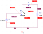
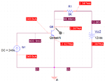
I have simulated the circuit with orcad and get the bias point for Ib=24ua and 240ua with the QbreakN transistor with BF=100
and I've attached them
at Ib=24u
Ic=2.356ma
Vce=.2223 V


at Ib=240u
Ic=2.387ma
Vce=.0669V


I've noted that
at Ib=24ua Vce=.2V(then it's saturated)
at Ib=24ua Vce=.0669V(then it's fully saturated)


and the difference between the Ic in the two state is 31uA
it means in the two state the transistor is saturated

if any thing is wrong pls adviceCE-NPN-IB24u.pngCE-NPN-IB240u.png
 

I did never say that the hFE I was using was 100 when the transistor is working as amplifier, I just took it as the minimum value.

But you must not use the hFE shown at the chart (mostly min, typ and max values) but the one which figures at the hFE vs IC graph.

Obviously you have to use the minumum hFE for your application, otherwise you won't assure that the transistor is correctly switching. Sometimes, for low and medium current hFE is about half the value given, or not so far from it, it's a design approximation.

What you should do is to check it at the graph I told you.

Anyway if you want to switch low currents, hFE won't be a problem since most medium current transistors can reach at least 70 or 100 (minimum).

Sorry about not telling you about that.
 

Hi Audioguru
I have simulated the circuit with orcad and get the bias point for Ib=24ua and 240ua with the QbreakN transistor with BF=100]
Sim programs usually use the spec's for a "typical" transistor that you cannot buy. You might get one with minimum spec's so your circuit will fail if you use typical specs but your transistors have spec's less than typical. Maybe the latest production run produced passable transistors but all had less than typical spec's.

- - - Updated - - -

I did never say that the hFE I was using was 100 when the transistor is working as amplifier, I just took it as the minimum value.

But you must not use the hFE shown at the chart (mostly min, typ and max values) but the one which figures at the hFE vs IC graph.

Obviously you have to use the minumum hFE for your application, otherwise you won't assure that the transistor is correctly switching. Sometimes, for low and medium current hFE is about half the value given, or not so far from it, it's a design approximation.
No again.
The datasheet for the 2N3904 transistor that I previously showed the saturation specs has a graph of hFE vs collector current at different temperatures but only when it is an amplifier with Vce= 5V so it is not saturated. The graph shows the hfe only for a "typical" transistor that you cannot buy. The hfe is 230 when the collector current is 0.1mA to 10mA and the hFE drops to 150 when the collector current is 100mA.

The datasheet also has a graph of Vce saturation voltage at different temperatures but only for a "typical" transistor that you cannot buy. The graph has the base current at 1/10th the collector current, not 1/230th. The saturation voltage for this "typical" transistor is 1/4 that of a minimum spec transistor that also has a base current 1/10th of its collector current.
 

Status
Not open for further replies.

Part and Inventory Search

Welcome to EDABoard.com

Sponsor

Back
Top