Continue to Site

Welcome to EDAboard.com

Welcome to our site! EDAboard.com is an international Electronics Discussion Forum focused on EDA software, circuits, schematics, books, theory, papers, asic, pld, 8051, DSP, Network, RF, Analog Design, PCB, Service Manuals... and a whole lot more! To participate you need to register. Registration is free. Click here to register now.

Spwm filter design (lc filter)

Status
Not open for further replies.

HARSHID1993

Newbie level 6
Joined
Aug 26, 2014
Messages
14
Helped
0
Reputation
0
Reaction score
0
Trophy points
1
Activity points
89
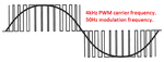
I have designed SPWM inverter and i got waveform as show in fig but problem is that i want to convert that waveform in to sine so i refer many of LC type filter but i didn't find any of proper method for that.
following are specification of inverter:
1:eek:utput frequency -50Hz
2:switching frequency - 4KHz
3:eek:utput voltage-230VAC
4:eek:utput current:5A

please help me out for above problem. fig5.png
 

try the **broken link removed** and desing a simple low pass filter.
 
  • Like
Reactions: Sonic

    Sonic

    Points: 2
    Helpful Answer Positive Rating
try the **broken link removed** and desing a simple low pass filter.

Oki.
But do you have n e idea for that filter design..
Means selection of cutt of frequency an all that.??
 

[Moved]Low Pass Filter design for power inverter

I tried every of paper for filter but i didn't get pure sine..
please help me out for this if u find some way
 
Last edited by a moderator:

You never told what you are exactly trying (circuit, achieved waveforms)
 

you never told what you are exactly trying (circuit, achieved waveforms)

i am trying to get pure sin so i need circuit and design for filter.
Please if you have any idea reply asap.
Dead line is near for that.
 

Your filter network needs to maintain the entire load during gaps in the PWM. A capacitor will do this job (with a small inductor in series, to soften spikes).

Put an inductor in series with the load, to smooth the pulses.


My simulation uses a slower carrier frequency (1.5 kHz), to make it easy to observe the PWM waveform. Since your carrier frequency is faster, you can reduce the coil and capacitor values.
 

I fear, a real output stage won't like the series resonance circuit tuned to the PWM fundamental.
 
There may be a better way. (I had forgotten about this.)

There is no need to expose the capacitor to massive current spikes. A second order lowpass filter is able to do the job.

It is much easier to obtain smooth sinewaves.


The SPWM pulses come from one op amp for 1/100 second, then from the other op amp. The filter network sees ground at each end during idle gaps. (In my post #7, it sees high impedance.)

Two op amps create a simple H-bridge. At 7A this is only possible in simulation.

A real H-bridge will need the proper control signals.

hey thanx for your support
my que is still that how can i design that filter which you had upload..have you any theory or related note for it.??
please give some tips if you have.........
 

hey thanx for your support
my que is still that how can i design that filter which you had upload..have you any theory or related note for it.??
please give some tips if you have.........

Although I'm not certain, I think values can be determined using an online woofer crossover calculator. Choose 2nd order, and your load resistance, and a frequency between the fundamental (50 Hz) and your carrier (4000 Hz).

The concept behind turning a square wave into a sine, is that the inductor should create a L/R time constant, so that current rises gradually. Maximum current should be reached less than halfway through a pulse.

As for the capacitor, its R*C time constant should likewise allow it to charge quickly about halfway through a pulse, then discharge to the load. It then starts to impede current through the coil, since its charge has become greater than the square wave's amplitude.

The sum effect is to create a sinewave at the load. Its peak amplitude is greater than that of the incoming square wave.
 
Can you please give that url from where you found your answer.....


Why isn't the PWM modulated at 50Hz?? Then it will not have 3rd, 5th, 7th, 9th, 11th, and many more harmonics. It will be simple to filter out the 4kHz carrier frequency.
 

Attachments

  • PWM waveform.png
    PWM waveform.png
    35.7 KB · Views: 227

Try an LC low pass filter at 300HZ cut off frequency. that will vanish the 4KHZ frequency. The filter type must be butterworth and the insertion loss at 50HZ must be less than 1 db.
 
hey Cutoff frequency selection is like this ??
10*(signal fre)<cut-off fre<(switching fre)/10

i am correct?
 

as a rule of thumb yes. You could check a lot frequencies and see the cut off in 4KHz what will be. The program calculate all automatically and gives you the results you need. For example in 3 order filter you may have 20db attenuation in 4KHZ but careful because it needs space. Coils are in toroid and that need space. If you like high currents the wire must be fat that leads you to bigger toroid. Also a litz wire will help you. When you calculate your filter you could see how big are your coils.
Another thing is the input output impedance you like the filter have on that frequencies. The input output impedance make your coils bigger or smaller.
Hope you have time for experimentation.
 
4kHz is very audible and will drive you crazy if it runs a motor. Wheelchairs use PWM at least 25kHz so it is not heard by people (only dogs). These higher frequencies use smaller coils and capacitors.
 

yeh correct.
for that i am going to design my PWM on 20KHz.
but i think first of all i want to learn how to design a filter for any Inverter so i used this 4KHz..

thankxx for your support

- - - Updated - - -

An online calculator is a quick way, of course.

I played with values in a simulator to find LC values. It's educational although time-consuming.

Use the crossover calculator for 2nd Order (12 dB per Octave) (Butterworth):

www.the12volt.com/caraudio/crosscalc.asp#ccc

www.diyaudioandvideo.com/Calculator/XOver

As it turned out my LC values are for a 22 ohm load, and 1000 Hz.

hey i didn't get sine wave i got square wave from the circuit which u gave me via 2 link.....
did got output via that circuit??
 

take a look on the sample filter. At 50HZ the attenuation is about 0.2db and at 4KHZ 100db.
 

Attachments

  • Filter_example.zip
    12 KB · Views: 151
Status
Not open for further replies.

Similar threads

Part and Inventory Search

Welcome to EDABoard.com

Sponsor

Back
Top