Welcome to our site! EDAboard.com is an international Electronics Discussion Forum focused on EDA software, circuits, schematics, books, theory, papers, asic, pld, 8051, DSP, Network, RF, Analog Design, PCB, Service Manuals... and a whole lot more! To participate you need to register. Registration is free. Click here to register now.
I can´t see any problem to do that, just by supplying different states at each one, although can´t see any advantage, once this way you waste 2 pins of the uC performing the same task.
This can be solved depending on sensor logic when A&B are active high or low. Which sensor?
If A&B = 1 for LED= On using high side driver. AND logic
If A&B = 0 for LED= On using high side driver NOR logic
If A&B = 1 for LED = On using low side driver NAND logic
If A&B = 0 for LED = On using low side driver OR logic.
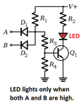
If sensor can drive LED as indicator with 5 mA, then no driver is needed , just 2 diodes for logic and current limiting R based on Ohms Law for drop voltage.
Otherwise if cannot drive 5mA, any device with sufficient low impedance can switch diode on with series R added, as Audioguru has shown for example.
Even if rated, 20mA may be overkill for an indicator.
You can make an AND gate as someone said before, just using diodes. Since a common diode voltage drop is 0,7v and the LED is 2V, and your supply is 5V (higher than that) you may not need driver such as a transistor.
Just connect a resistor to +Vcc, then connect it to the LED and both AND gate diodes annodes to the LED cathode.
If your IC can drive 3mA (or any current you want, just calculate it with the resistor) you have the circuit done.
This site uses cookies to help personalise content, tailor your experience and to keep you logged in if you register.
By continuing to use this site, you are consenting to our use of cookies.