Continue to Site

Welcome to EDAboard.com

Welcome to our site! EDAboard.com is an international Electronics Discussion Forum focused on EDA software, circuits, schematics, books, theory, papers, asic, pld, 8051, DSP, Network, RF, Analog Design, PCB, Service Manuals... and a whole lot more! To participate you need to register. Registration is free. Click here to register now.

Baxandall filter circuit

Status
Not open for further replies.

Woody2

Newbie level 6
Joined
May 13, 2014
Messages
13
Helped
0
Reputation
0
Reaction score
1
Trophy points
1
Activity points
119
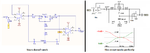
I've built a baxandall circuit for use as a guitar effect.
The circuit is below, wich is a combination of multiple schematics I found online.


I've built this thing and I get weird results, when I connect it to my guitar amplifier it farts out. (short clicking sounds when I hit a string)

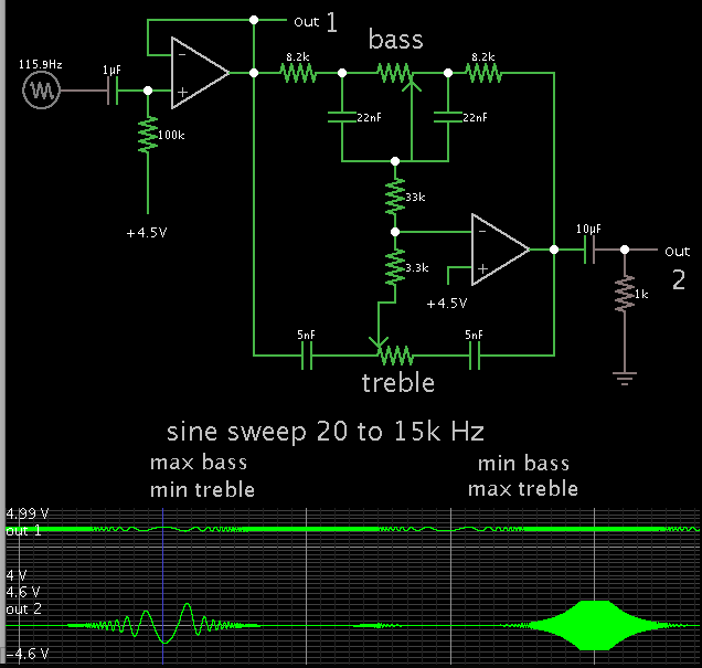
When I inspect it with an oscilloscope, I find that the bass & treble controls work, however I can still roll of 100Hz with the treble and at the same time I can roll off 10kHz with the bass control. Just not as much as with the dedicated controls.

I've calculated and simulated the circuit, the roll-off frequencys are 88Hz and 4107Hz with Av≈12

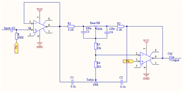
Do you guys see any errors of sorts? I've seen people use a cap between opamp 1 and the filter, but I'm not sure what for.
 

It looks reasonable to me. Do you have both the points marked 'Vb' connected to a supply of half VCC? If not, connect two 10K resistors in series across ground and VCC and use the center connection as the 'Vb' supply. You have not marked what kind of amplifiers you are using or what VCC actually is, be careful if using older op-amps because they may need a higher supply than you are providing.

Brian.

I forgot to mention, my bad

I'm going with the industry standard of guitar pedals wich is 9V Vcc. I used a voltage divider for Vb like you said.
For now I'm using TL072 opamps, wich should be fine cause I also made a variable mid section wich works.

I'm glad you said that it seems OK because I was really starting to think I had done something wrong in the circuit. My knowledge of opamps isn't the best.

Thanks, I guess I'll start checking and replacing some components
 

The circuit also appears OK to me.

I'm with Brian on this one. Either the Vb supply is of the wrong value or the total supply voltage for the particular opamp you are using is not enough.

Please provide the details of the circuit that provides Vb, the total supply voltage and what type of opamp you are using.

See my post above :grin:
 

Cross posting!! Your post arrived while I was writing the reply.

9v is little for a TL072 opamp on a circuit that requires gain, like the Baxandall circuit. You will run out of output swing and common mode input range which causes the farting.

You can use the TLC072 version instead.
 

Cross posting!! Your post arrived while I was writing the reply.

9v is little for a TL072 opamp on a circuit that requires gain, like the Baxandall circuit. You will run out of output swing and common mode input range which causes the farting.

You can use the TLC072 version instead.

Oh, that would make sense, I'll see if I can find one of those.

Thanks alot.
 

Use this circuit that works.
I agree that the TL072 has a problem (Opamp Phase Inversion) when the input signal level gets too high.
 

Attachments

  • tone controls.png
    tone controls.png
    46.9 KB · Views: 61

For comparison (and for the fun of it), here is a screenshot of an interactive simulation.


The input signal can have an amplitude on the order of 1/2 V.

The op amp outputs are set for a range of 0 to +9V.

I adjusted capacitor values, in order to bring out the cut/boost action better.
 

Status
Not open for further replies.

Similar threads

Part and Inventory Search

Welcome to EDABoard.com

Sponsor

Back
Top