Continue to Site

Welcome to EDAboard.com

Welcome to our site! EDAboard.com is an international Electronics Discussion Forum focused on EDA software, circuits, schematics, books, theory, papers, asic, pld, 8051, DSP, Network, RF, Analog Design, PCB, Service Manuals... and a whole lot more! To participate you need to register. Registration is free. Click here to register now.

Doubt parallel stage class AB amplifier

Status
Not open for further replies.

julian403

Full Member level 5
Joined
Feb 28, 2014
Messages
254
Helped
1
Reputation
2
Reaction score
1
Trophy points
18
Location
Argentina
Activity points
2,105
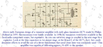
I'm making an class AB amplifier and I must to do it with a simple source of 12 [V].

circuito.png

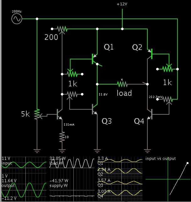
I did all the calculations for the polarizations. Where the fall in each transistor is Vcc / 2 and in this case is 6 V. For more power I put a transformer to the load. My first question is this. With a ratio of 1: 3 I have a power of 21 W but with a ratio of 1: 2 or 1: 4, that is, more or less I have a minimum power why?

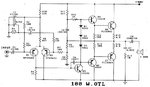
A friend said to me that I can put another power amplifier in parallel for more power. But if I put two parallel stages I do not get twice, but a bit more than one . I mean I don't get 42 Watts but 33 Watts.

circuito2.png

But if I change the value of the transformer ratio 1:3 to 1:4 I get twice the power. Why?

circuito3.png

For every step that I put I up the number of turns of the secondary one for twice the power

From already thank you for the help
 

Hello,

Kindly refer to the datasheet of TDA7293. The concept of bridging and paralleling are explained. If you have any further doubts there after, we can discuss it here.

I hope that this helps.
 

The level of your input signal is way too high at 18V peak-to-peak. It should be only 5V peak if the transistors have typical spec's and be only 4V peak if the transistors have minimum spec's.
But the value of your 22uF input capacitors is too low so is reducing the input signal level to the output transistors.

I guess you have never seen the schematic of a fairly high power amplifier because two capacitors at its input was used 59 years ago only for very low power amplifiers.
Modern high power amplifiers do not use parallel amplifiers instead they use more powerful transistors or parallel output transistors. They do not use output transformers.
 

Attachments

  • Philips transistor amp-1955.PNG
    Philips transistor amp-1955.PNG
    186.7 KB · Views: 96
  • 100W amplifier.png
    100W amplifier.png
    254.1 KB · Views: 125

Yes But I use a source of 12 [V] not one of 90 [V]. For that reason I use the transformers, to get more power. Because I'm looking an output between 80 to 100 Watts. Do you think that this capacitor will generate noise? I must put electrolitic?
What I simulated the circuit in multisim and no cut in the signal. It's weird because the greater the number of turns in the transformer secondary winding is less the reflected resistance and should be more power but decreases.

Regarding the parallel setup, viewing the schematic attached to the TDA7293 datasheet, I see the parallel configuration I did okay. Am I right?

esquematico.png
 

Hi,

Check the voltage across the 1mF capacitor. With higher transformer ratio the amplifier sees increasing load resistance.
But the capacitor impedance is constant. The lower the load resistance, ghe higher thevoltage drop across the capacitor.
...the less voltage at your transformer...the less power at your speaker..

With a constant load (4Ohms) and a 1:3 transformer ratio the resulting primary impedance at yor transformer is: (1/3)^2 * 4 Ohms = 0.444 Ohms. (With ideal devices). With 1:4 it is 250mOhms.

Klaus

Klaus
 
Do you think that this capacitor will generate noise? I must put electrolitic?

Since you are adding another half-bridge...

You might as well consider a bridged arrangement (as recommended in post #2). This is a full H-bridge. The load is the 'bridge'.

Then you will not need the DC blocking capacitor.

You will get output of +-12 V, rather than +-6V. (Peak values.)

12V peak translates to 8V nominal AC.
6V peak is about 4V AC.
To obtain 80W at 8VAC, you'll only need 10 A going into the transformer.
However at 4VAC, you'll need 20 A.

The transformer performs impedance matching as one of its jobs. This is one reason why you notice it improves power transfer.
The other part of its job is to step up voltage. A 4-ohm speaker needs 13VAC to drive it at 42 W. But you could not obtain this at first. You needed to step up the ratio.
 
Audioguru;
I also remember with fondness the early designs of transistorized audio amplifiers, which produced miniscule outputs.

The inclusion of a driver transformer became standard afterwards, and substantially helped with the coupling.

Of course, with those early germanium power transistors in the TO-1 case, one would not get even a full watt.
 
Just two things. I do not know what a full H-bridge it is. And if I do not put the capacitor of 1 mF there is a component cc in the load. What can i do? because I can't get it away.
 

Yes But I use a source of 12 [V] not one of 90 [V]. For that reason I use the transformers, to get more power. Because I'm looking an output between 80 to 100 Watts.
Transformers were used in old vacuum tube amplifiers, not in modern high power amplifiers used in cars. A modern high power car amplifier uses a voltage stepup circuit so the resulting 56VDC powers a 100W amplifier. Bridging two amplifiers is also used with or without a voltage stepup circuit. I had a car that used bridged amplifiers driving 2 ohm speakers to 26W when the supply was 13.2V.
With two bridged amplifiers a supply of 31VDC is needed for 100W into 4 ohms.

Do you think that this capacitor will generate noise? I must put electrolitic?
I do not know which capacitor you are talking about.

What I simulated the circuit in multisim and no cut in the signal. It's weird because the greater the number of turns in the transformer secondary winding is less the reflected resistance and should be more power but decreases.
Your little output transistors have a fairly low maximum allowed current of only 6A. Your simple circuit is missing driver transistors so maybe the output transistors cannot supply peaks of 6A.

Regarding the parallel setup, viewing the schematic attached to the TDA7293 datasheet, I see the parallel configuration I did okay. Am I right?
The datasheet for the TDA7293 says its MINIMUM supply is 24V but you have only 12V. Their parallel amplifier circuit is used to drive a very low load impedance (many speakers in parallel) that you do not have.

- - - Updated - - -

Just two things. I do not know what a full H-bridge it is.
It is two amplifiers in a bridge. One amplifier drives one wire of a speaker and the other amplifier drives the other wire of the speaker with reversed phase. Then the voltage and current swings in the speaker are almost doubled resulting in about 3.5 times the power of a single amplifier driving the speaker. Also since you have a single supply voltage a single amplifier needs an output capacitor that cuts low frequencies and cuts output power, but a bridged amplifier does not need an output capacitor.

And if I do not put the capacitor of 1 mF there is a component cc in the load. What can i do? because I can't get it away.
1000uF is too small for deep bass into 4 ohms. 40Hz will be at half power. Lower frequencies will have less power.
The output capacitor in your circuit blocks the DC at the output of the transistors from destroying the speaker.
 
Just two things. I do not know what a full H-bridge it is. And if I do not put the capacitor of 1 mF there is a component cc in the load. What can i do? because I can't get it away.

This simulation illustrates an H-bridge driving a 4-ohm load. Amplitude is nearly the entire supply voltage.

To create an inverted signal at the left, an NPN transistor is used.

This circuit illustrates a concept. It is not the circuit you should build. It wastes a lot of current when idle. A proper circuit will turn off transistors completely. (For instance Q2 is not getting a 12V bias voltage which it needs to turn off.)

There are proper H-bridge amplifier schematics available on the internet.


Check what I did. I get a power of 41 W. It's okay? Do I need the Re resistor of 0.1 Ω? because without it I get a power or 54 Wat.

circuito.png

Can I put another steps equal to the attached in parallel to obtain twice the power would be 100W?
 

I said it before, your input signal is way too high. It should be about 5V peak if you increase the value of the 22uF input capacitors so that they pass deep bass sounds.

If the output of each pair of transistors idles at +6V and their maximum voltage is +1V and +11V then the peak input and output voltage is 5V.
With an input peak of 5V then the RMS output is about 4.5V x 0.707= 3.2V RMS. The bridged circuit doubles the output swing to 6.4V RMS and the transformer doubles it to 12.8V RMS. Then the output power is (12.8V squared)/4 ohms= 41W.

But the input capacitors should be replaced with a driver transistor and single collector resistor for it. Negative feedback should be used to stabilize the DC biasing and to reduce distortion.
A custom made output transformer will be very expensive and will reduce low and high audio frequencies.

- - - Updated - - -

Can I put another steps equal to the attached in parallel to obtain twice the power would be 100W?
What is "another steps"? Use a 1:3 transformer?
100W into 4 ohms is an RMS current of 5A. The peak current is 5A x 1.414= 7.07A. The transformer will increase the peak current in the transistors 3 times to 21.2A which will blow up your little output transistors that have a maximum current rating of only 6A.
 
Check what I did. I get a power of 41 W. It's okay?

Yes, things are gelling. You have the concept working.

When we put the NPN's on top, we need to drive them at the same amplitude we want to see at the load.

Trying changing the load to draw more power. You may manage to get 80-100 W as you specified. Try changing transformer parameters.

Do I need the Re resistor of 0.1 Ω? because without it I get a power or 54 Wat.

A number of similar amplifier designs have a resistor in the emitter leg (such as Audioguru's post #3). These are a good idea as a safeguard.

The resistors are like fuses. Better for them to fail rather than power transistors.

Can I put another steps equal to the attached in parallel to obtain twice the power would be 100W?

Yes, you can add transistors in parallel if you wish. Check that the bias current is sufficient to drive them. The bias current comes from your incoming signal.

Did you adjust values in order to get all you can out of your present circuit?
 
The 0.1 ohm emitter resistors allow NPN and PNP transistors with different spec's to operate more equally. The resistors add negative feedback that reduces distortion.
 

Hi,

The 0.1 ohm emitter resistors allow NPN and PNP transistors with different spec's to operate more equally. The resistors add negative feedback that reduces distortion.

i always thought they are for compensating thermal drifts and thus stabilize operating area.
But this also improves distortion.


Klaus
 
I always thought the emitter resistors are for compensating thermal drifts and thus stabilize operating area. But this also improves distortion.
The diodes should be mounted on the heatsink of the output transistors for thermal stability. Then when the output transistors heat and conduct more current which causes them to heat more and conduct more current .... (thermal runaway) they also heat the diodes which reduces their forward voltage which reduces the base-emitter voltage of the transistors which reduces their current increase to almost nothing.
The emitter resistors make the base-emitter + resistor voltage more equal between unmatched transistors and increase the linearity of the base-emitter voltage as the changing current changes it.
 
Did you adjust values in order to get all you can out of your present circuit?

Yes I did. But there is one things that I worry. If I changes the value of rate transform in the way that the load of 4 Ohm will be more little. For example for one steps I get, with a relationships of 1:3, a the maxium value of power. So with a relationship of 1:4 and 4 ohms I get a load of 0.44 ohms an Ic = 7[A] peak. The transitor support 6 [A] and 10 [A] peak, that can be the reason of if I change the relationship to bigger, i mean 1:4 for example, the power get down??.
 

To conduct more current the transistors need more base current but you are not increasing the base current.
The minimum current gain is spec'd to be only 15 when the current is 3A. The minimum current gain is not spec'd when the current is higher. At 7A it might be nothing.
Why don't you use transistors that have a good current gain spec when the current is high?

Why are you still using two input capacitors instead of a driver transistor??
Why are you still using a very expensive custom-made transformer at the output?
 
Julian this design approach you are taking will not result in high quality sound. There are many reason's nobody uses transformers to boost power to speakers from a 12V Amplifier. But if you don't mind 10-20% distortion at rated power, it's ok.

A stepup transformer increases the source impedance of the amplifier xN squared. Even an ideal distortion free signal gts distorted by the inertia of motion forced on the speaker coil. The amplifier tries to be a "voltage source" with near ideal zero source impedance, so that the cone follows the signal tightly. This ratio of load to source is called Dampening Ratio because when this typical ratio is reduced dramatically increases THD at rate power. ( It may be ok at low power but at high cone motion, back EMF of the coil will add distortion to the signal when the power rises. ) Typically it is of 50:1 in low power units and 500:1 in high and extreme cases are higher and lower..

In DC power supplies it is called Load Regulation where a typical spec. of a good power supply might be 1 or 2 % meaning ! Source/load impedance is 1 or 2%. Any step loads near full power would result in ripple or distortion by this amount. This ripple can occur with just a resistive load and audio system, there are also reaction forces of moving air and coil so it also has some back EMF.

You might want to reconsider your requirements for power and quality.
 
Status
Not open for further replies.

Similar threads

Part and Inventory Search

Welcome to EDABoard.com

Sponsor

Back
Top