Continue to Site

Welcome to EDAboard.com

Welcome to our site! EDAboard.com is an international Electronics Discussion Forum focused on EDA software, circuits, schematics, books, theory, papers, asic, pld, 8051, DSP, Network, RF, Analog Design, PCB, Service Manuals... and a whole lot more! To participate you need to register. Registration is free. Click here to register now.

Electronic for diging machine

Status
Not open for further replies.

Zajic Vladimir

Newbie level 4
Joined
Aug 12, 2014
Messages
5
Helped
0
Reputation
0
Reaction score
0
Trophy points
1
Activity points
45
Hi, I see this forum and decite to write a problem so if anyone can help.

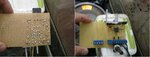
My uncle have a diging machine whith electronic is broken and some home made electronic man make some stuf to work but it is too bad (will see on the pictures). It is working but my uncle want it to be better.

Electronic job is to control valve for oil presure.

So: here is links and info for problem

This is the valve for controling:
**broken link removed**

I believe this is fabric electronic for controling valve:
https://www.google.rs/url?sa=t&rct=...1t-VEKMmzpVXj9cVg&sig2=3svQvTS7D3oUJ2_hhJuVaA

And on pictures uploaded you can see how home made electric man make to work.
I search on internet and see a lot od step dpwn converter and similar things whis is cheap to buy because fabric electronic is too expencive.

Soo if anyone can help me to find right electronic for my problem I will be vey thankeful, because I dont have enough expirience in this world.
 

Attachments

  • 2.jpg
    2.jpg
    1 MB · Views: 69

If it works ---- it works!! What it needs is to be put in a proper box, have proper latched connectors on the outside of the box, have the circuit diagram printed out and put in the box and finally the terminal board labelled so you know whats what. Doing this will increase the cost of the project (~£2 in bits) to about £20 ( that is why he did not do it).
Frank
 

It's not that bad a of job, yes it looks ugly, but all the soldering looks decent enough.

If your uncle wants a production ready version then expect to spend some time and money drawing out the schematics as suggested in #2. Enter that in a CAD program and make a printed circuit board. I'd suggest using a layout similar to the one on the current ugly board. Then put it in a "pretty" box with quality latched connectors as suggested in #2.
 

The original has no display. If you want to have a display , it should be meaningful. The easiest thing to do is to measure the average voltage across the valve solenoid, though how you convert this into something that makes sense is beyond me. You could instal an oil pressure transducer and from that have a display calibrated in PSI, though if this would mean anything to the driver is another thing.
Frank
 

Oil pressure I thingk is regulatet with voltage. If voltage is lower - turning potentiometar closer to zero for example presure is low. And inversely. We checked on this home made thing and it is that when we turning potentiometar to zero pressure is lower and inversely too.

So, we need electronic which have display to showiing the current value of voltage. I meen, there is no need for regulation of amps??? We thing that voltage is important for regulation???
 

As far as I can make out, the valve operates by changing the voltage across it. As its a solenoid (resistor), the current through it depends on the voltage. I = V/R.
You can regulate the valve by putting a resistor in series with it to reduce the voltage, but it would use a lot of power so would have to be BIG. Also it would have to be adjustable which would make it a very expensive component.
What this circuit does is to pulse (switch) the voltage on and off, if its on for 100% of the time, the valve is being fed from 12V, if the voltage is pulsed on for 50% of the time, its like the valve is being fed from 6V. if you try and measure the voltage directly, you could fool your self depending on the meter as its not a continuous 6V, but a series of 12V pulses. A few cheap components would filter the pulses enough to give you an accurate DC voltage which you can then measure.
Frank
 

Hmm. Soo what is your sugestion?
This valve regulated oil pressure of the main valve which regulatet speed of the machine.

Do you think that cheap electronic from internet like step down converter can do the job?
Or mabye some other cheap electronic?
With dispaly.
 

It's not yet obvious that your machine needs an electronic control at all. The majority of hydraulic drives is still controlled by pure mechanical valves, e.g. with construction machinery. Before you design an electronic controller you should be clear about it's specific purpose.
 
We just need a some electronic which control oil flow through valve. I see that step down converter can decrease voltage which is we suppose what we need.

On user manual of the valve is parameters needed for controlling, we just asking is there any appropriate electronic for that.
 

O.K. The datasheet suggests 200 Hz PWM frequency and assumes constant current operation.
 

Status
Not open for further replies.

Similar threads

Part and Inventory Search

Welcome to EDABoard.com

Sponsor

Back
Top