sakibnaz
Full Member level 3
Hi.
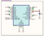
For my project I used uBlox CAM-M8Q. Attached is the schematic. Here V2-3.3v which is output of a LDO.
But when I am observing the GPS UART data I can see the 3D Fix not occurred. Below are the captured data:
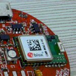
I am using internal Chip antenna of the Module.
Can anyone advise me on my Schematic? Is the any initialization command needed to issue to make the 3D-Fix?
Thanks in advance.
Regards.
For my project I used uBlox CAM-M8Q. Attached is the schematic. Here V2-3.3v which is output of a LDO.
But when I am observing the GPS UART data I can see the 3D Fix not occurred. Below are the captured data:
> $GNVTG,,,,,,,,,N*2E
> $GNGGA,,,,,,0,00,99.99,,,,,,*56
> $GNGSA,A,1,,,,,,,,,,,,,99.99,99.99,99.99*2E
> $GNGSA,A,1,,,,,,,,,,,,,99.99,99.99,99.99*2E
> $GPGSV,1,1,00*79
> $GLGSV,1,1,00*65
> $GNGLL,,,,,,V,N*7A
> $GNRMC,,V,,,,,,,,,,N*4D
I am using internal Chip antenna of the Module.
Can anyone advise me on my Schematic? Is the any initialization command needed to issue to make the 3D-Fix?
Thanks in advance.
Regards.