Continue to Site

Welcome to EDAboard.com

Welcome to our site! EDAboard.com is an international Electronics Discussion Forum focused on EDA software, circuits, schematics, books, theory, papers, asic, pld, 8051, DSP, Network, RF, Analog Design, PCB, Service Manuals... and a whole lot more! To participate you need to register. Registration is free. Click here to register now.

ECG Amplifier using INA321 and OPA336

Status
Not open for further replies.

vorashrenik

Newbie level 5
Joined
Jul 28, 2010
Messages
9
Helped
1
Reputation
2
Reaction score
1
Trophy points
1,283
Location
Philadelphia
Activity points
1,350
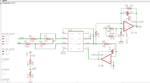
I am trying to make a simple ECG amplifier using INA 321 and OPA 336. I am driving this amplifier using a an ECG simulator(https://www.heinstruments.com/ecg-simulator.htm), hence I do not have a right leg drive circuit.
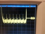
My schematic is attached. I have made the circuit on a breadboard for now, the problem that I have is that it works for a few seconds and then stops. The problem seems to be with the INA321 and the feedback opamp used for the reference. I have attached a snapshot of the scope that shows the output turning off.

Any ideas on why this might be happening?
 

Attachments

  • 20140808_162710.jpg
    20140808_162710.jpg
    1.9 MB · Views: 119
  • schematic.png
    schematic.png
    30.9 KB · Views: 136

The simulator does provide a right leg terminal so why don't you use it? In any case an instrumentation amplifier needs some means to enforce a common mode voltage in the specified range. If you don't use a RL circuit, you must have Mohm bias resistors to ground at the inputs.
 

I thought that is what R7(1Mohm) and R8(1Mohm) are doing (both connected to VR which is half the rail voltage).
In fact, when the output stops it runs to 2.5V which is the common mode voltage (VR).
I am not using the RL circuit, as this is just for some simple proof of concept and I think that it is not critical to the functioning of this circuit with the simulator.
 

Sorry, I overlooked the connection to VR. It should work this way.

Reviewing the INA312 datasheet details, I noticed that the SD pin must be connected to VCC. Missing connection might explain the observed behaviour.
 

Though not on the schematic, I did end up connecting the SD pin to VCC but it didn't stop the issue. Here are some other things that I tried:
1. Disconnected R6 and checked the output at the instrumentation amp to rule out the final opamp as the issue.
2. Removed the voltage divider and supplied VR using a separate power supply.
None of the above solved the issue.
 

No. Maybe there's a problem with the simulator output DC-level. In a first test, I would check levels of all INA321 signal pins for plausibility.
 

Status
Not open for further replies.

Similar threads

Part and Inventory Search

Welcome to EDABoard.com

Sponsor

Back
Top