f_t
Member level 4
Friends,
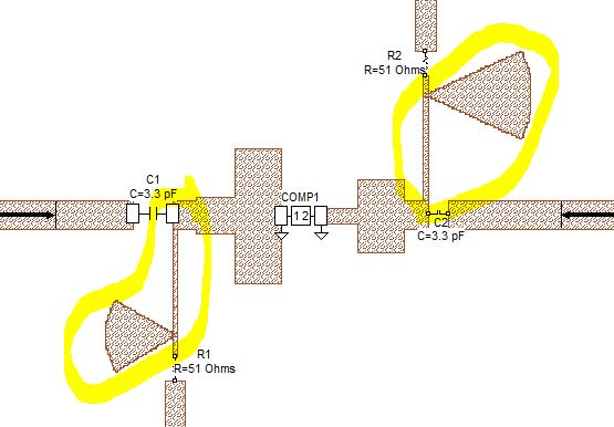
Could you please tell me in what situation I should use which kind of inductors? I mean as you see in the photo, the first one is a conventional inductor, the second one is a Mline, and the third one is spiral (My circuit is not a Ic and is a discrete circuit).
To supply drain of a power amplifier (which passes high current) I should use a conventional inductor or a RF choke or Mline (2.3 Ghz working frequency)?
What about in a matching or filter network which work at 2.3 GHz?
when should I use a spiral one? I think when there is no high current which wants to pass through the inductor, but what about its frequency? low or high?
Thanks