Continue to Site

Welcome to EDAboard.com

Welcome to our site! EDAboard.com is an international Electronics Discussion Forum focused on EDA software, circuits, schematics, books, theory, papers, asic, pld, 8051, DSP, Network, RF, Analog Design, PCB, Service Manuals... and a whole lot more! To participate you need to register. Registration is free. Click here to register now.

fm transmitter circuit not working?

Status
Not open for further replies.

rata478

Junior Member level 1
Joined
Aug 2, 2014
Messages
16
Helped
0
Reputation
0
Reaction score
0
Trophy points
1
Activity points
111
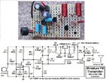
I followed a simple fm transmitter circuit using a "circuit simulator" i found on the internet: http://www.falstad.com/circuit/

circuit: FPRK3CDHXRU3W14.MEDIUM[1].jpg

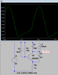
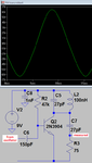
circuit i made in circuit simulator v1.6h:
Untitled.png

Why is the output signal not pulsating?
Is there something wrong with the simulator or did i just do something wrong?

Thankyou in advance. :)
 

Check on simulator netlist if the transistor placed on circuit is really the 2N3904, due this information is not visible on your circuit. By the way, it was suggested on the article bellow original schematic to perform fine tunnings, did you that ?
 

Check on simulator netlist if the transistor placed on circuit is really the 2N3904, due this information is not visible on your circuit. By the way, it was suggested on the article bellow original schematic to perform fine tunnings, did you that ?

Yes i did.

- - - Updated - - -

should i just physically build it and see what happens or try a different software?
 

I´m not totally sure, but presume such circuit do not provide any carrier unless having a signal becoming from first stage amplifier due I can´t identify any positive feedback on RF amplifier stage for generate a self-oscillation, so that you probably must simulate by insertion of a sinewave low impedance voltage source there, as drawn on original circuit.
 

It is the hopeless circuit that I fixed 9 years ago.
1) It oscillates at 106MHz in LTspice IV program but only when it has no antenna. It produces many even harmonics so it causes interference. It stops oscillating when it has an antenna connected to the collector of the oscillator transistor.
2) The 10nF capacitor from the base of the oscillator transistor to +9V is WAY TOO BIG so it cuts all high audio frequencies. An FM transmitter is supposed to BOOST (pre-emphasis) high audio frequencies. My fixed circuit uses 470pf (3.4 ohms at 100MHz) so that 15kHz is not attenuated, and it also has pre-emphasis.
3) At 1kHz, the gain of the preamp is only 30 when it is feeding the 10k bias resistor of the oscillator transistor and the attenuation caused by the 10nf capacitor. Its gain should be at least 100 with the gain of higher audio frequencies much more.
 

Attachments

  • FM transmitter.png
    FM transmitter.png
    16.8 KB · Views: 117
  • FM tx mod4 pic and schematic.jpg
    FM tx mod4 pic and schematic.jpg
    196 KB · Views: 175
The aerial is dampening the tuned circuit too much. The capacitor connected to the collector should have a 100PF cap put in series with it at the Vcc end (not collector!). Connect the aerial to the junction of the new cap and the old.
Frank
 

I´m not totally sure, but presume such circuit do not provide any carrier unless having a signal becoming from first stage amplifier due I can´t identify any positive feedback on RF amplifier stage for generate a self-oscillation, so that you probably must simulate by insertion of a sinewave low impedance voltage source there, as drawn on original circuit.
The RF transistor is a common base amplifier (the 10nF capacitor "grounds" the base). Positive feedback from the collector to the emitter is through the 4.7pF capacitor.
I posted its simulation and it is oscillating at 106MHz.
 
In fact, I did not realized the amplifier as common base, but incorrectly read as a common emitter. Thanks for correct my previous assumption.
 

In fact, I did not realized the amplifier as common base, but incorrectly read as a common emitter. Thanks for correct my previous assumption.
Maybe the frequency modulation (FM) can be called common emitter. The audio signal at the base of the RF oscillator causes the capacitance of the transistor to change which causes the frequency of the oscillation to change (FM). It also produces a little amplitude modulation (AM).
 
монтесума.jpgхук.jpg
Similar schemes.
antenna issue will have to tinker.
 

View attachment 108172View attachment 108173
Similar schemes.
antenna issue will have to tinker.
The second transistor is the RF oscillator and it WILL NOT WORK because its emitter does not have a DC path to ground, and its output is shorted to +9V.
The third transistor is an RF amplifier but it is not biased so it causes many interfering harmonics because it operates in class-C.


That's right about the resistor you have written.
I made ​​a mistake in the mark of the scheme.
Thank you. Resistor must be moved to the left to set for constant current.
Google Translate unfortunately distorts the meaning part.
 

The second transistor is the RF oscillator and it WILL NOT WORK because its emitter does not have a DC path to ground, and its output is shorted to +9V.
The third transistor is an RF amplifier but it is not biased so it causes many interfering harmonics because it operates in class-C.

its ok to use class 'C' at FM
the output will be a sinewave
if the coil at the collector is tuned.
to the desired frequency
in all of the circuit shown no attempt
has been made to match the antenna
you can do this by taping the coil
the closer to the psu the lower the output impedance.
also remember that for maximum power transfer Rs=Rl. a 1/4 wave antenna at 98Mhz
approx = 0.76 meters the impedance
of this length approx = 50R,
you can use other lengths but you need to tune the antenna by either
placing a variable capacitor or inductance in series with it to obtain best results.
 

its ok to use class 'C' at FM.
The output will be a sinewave if the coil at the collector is tuned to the desired frequency.
The Russian article says the output is tuned to the second harmonic. I simulated the class-C RF amplifier and when it was tuned to the fundamental the distortion was pretty bad producing many harmonics and when it was tuned to the second harmonic the distortion was horrible with very many harmonics.

Look at this very nice low distortion sinewave from my class-A RF amplifier:
 

Attachments

  • FM RF sinewave.png
    FM RF sinewave.png
    15.4 KB · Views: 124

in the Russian circuit the Q of the coil at the collector in the class "C" must be poor.
try connecting the collector to a tap point. or may be change
the cap value in series with the base.
 

Status
Not open for further replies.

Similar threads

Part and Inventory Search

Welcome to EDABoard.com

Sponsor

Back
Top