Continue to Site

Welcome to EDAboard.com

Welcome to our site! EDAboard.com is an international Electronics Discussion Forum focused on EDA software, circuits, schematics, books, theory, papers, asic, pld, 8051, DSP, Network, RF, Analog Design, PCB, Service Manuals... and a whole lot more! To participate you need to register. Registration is free. Click here to register now.

Smps transformer design with copper foil/strip

Status
Not open for further replies.

jagdeepsingh3@hotmail.it

Member level 3
Joined
Sep 2, 2012
Messages
54
Helped
1
Reputation
2
Reaction score
2
Trophy points
1,288
Activity points
1,634
Smps transformer design with copper foil/strip Please help

Hi guys first i want to tell that my english is not good because i'm from itay :)

my problem is calculating transformer details (primary and secondry turns)

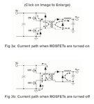
i'm using this circuit:
reg60v.png

HERE ARE THE PICTURES OF WAVEFORMS:

ON GATE DRIVER MOSFET:
GATE DRIVER MIN DUTY.jpgGATE DRIVER 35% DUTY.jpg

ON IGBT LOW SIDE GATE:
LOW SIDE IGBT GATE MIN DUTY.jpgLOW SIDE IGBT GATE GATE.jpg

INPUT VOLTAGE IS 230Vac
OUTPUT VOLTAGE IS 3Vdc TO 60Vdc
OUTPUT CURRENT IS: 60A MAX

i ha ve EE 70/33/32 CORE

**broken link removed**

CAN SOMEONE PLEASE HELP TO CALCULATING WINDING DETAIL WITH COPPER FOIL
THANKS IN ADVANCE ;)
 
Last edited:

Hi sir thanks for reply :)

i have a problem that my lcr meter is broken and i orderd new on and i don't know when it will arrive :)

and another main problem is calculating turns and dimension of copper foil can you please help me in that?
 

Hi sir thanks for reply :)

i have a problem that my lcr meter is broken and i orderd new on and i don't know when it will arrive :)

and another main problem is calculating turns and dimension of copper foil can you please help me in that?
Okay in this case you must read datasheet of your core as well and then you can use these formulas :
N=100sqrt(L/AL)
N=1000sqrt(L/AL)

( for iron powder and ferrite )
Best Wishes
Goldsmith
 

Thanks friend for helping me :)

i found this program can you please check if the calculations are fine?
Cattura.JPG
 

The calculator seems to give sufficiently thick wire sizes to carry your desired amperage.

For comparison, here is a table of wire gauges, and their ampacity.

http://amasci.com/tesla/wire1.html

Fortunately you're not winding a hundred turns. Just a few.

Have you tried a simulator to check your figures? There are free ones on the internet.
 

I think these are realistic numbers


2 transistor forward converter

Pri = 360vdc max, constant 4, 50khz, 1000 gauss, Ae 6.83 cm^2 = 26 turns

Sec = 60vdc at 283vdc min = 9 turns

- - - Updated - - -

Sorry i made some mistakes in my last post.
I used the wrong constant 4 instead of 2

Also i do not think you can put a full wave bridge on a forward converter. You must use the standard 2 diode output, one to rectify and the other for recirculation. Edit, never mind, i see it is not a full bridge now.

2 transistor forward converter

Pri = 360vdc max, constant 2, 50khz, 1000 gauss, Ae 6.83 cm^2 = 53 turns

Sec = 60vdc at 283vdc min = 12 turns
 

Attachments

  • forward 2 switch converter current flow.JPG
    forward 2 switch converter current flow.JPG
    57.5 KB · Views: 124
Last edited:

I think these are realistic numbers


2 transistor forward converter

Pri = 360vdc max, constant 4, 50khz, 1000 gauss, Ae 6.83 cm^2 = 26 turns

Sec = 60vdc at 283vdc min = 9 turns

- - - Updated - - -

Sorry i made some mistakes in my last post.
I used the wrong constant 4 instead of 2

Also i do not think you can put a full wave bridge on a forward converter. You must use the standard 2 diode output, one to rectify and the other for recirculation. Edit, never mind, i see it is not a full bridge now.

2 transistor forward converter

Pri = 360vdc max, constant 2, 50khz, 1000 gauss, Ae 6.83 cm^2 = 53 turns

Sec = 60vdc at 283vdc min = 12 turns


can you please explain why the constant is 2 ? and second thing 53 turns are too much :/

Cattura.JPG
 

Search for slup079.pdf
On page 7-41 Look at (EQ 9).
That is the formula i used.
This PDF is from Texas Instruments.

The program you used is just some individual guy who wrote it.

Pri turns = 360vdc x 10^8 / 2 x 50,000 hz x 1000 gauss x Ae 6.83 cm^2 = 53 turns
 

The difference between both calculations (11 versus 53 primary turns) comes from different designed Bmax values. Unfortunately neither the 450 mT nor the 100 mT number have been substantiated. A core loss and transformer temperature rise calculation should be performed. If you do it, you'll see that 100 mT ("1000 G") is not effectively utilizing the core but 450 mT and respective 16 W core loss will result in an probably inacceptable temperature rise.

The Epcos ferrite tool e.g. ends up with 270 mT for 25 K core loss related temperature rise (and suggests another 25 K for winding losses), which sounds all-in-all reasonable.
 

can give me the formulas to follow and the important variables to be respected please?
is very confusing on the books
thanks again
 

jagdeepsingh

Here is the link to the Epcos/TDK design software. I have not figured out how to use it.

Do you know what ferrite material you have, example N27 or N87

**broken link removed**
 

jagdeepsingh

Here is the link to the Epcos/TDK design software. I have not figured out how to use it.

Do you know what ferrite material you have, example N27 or N87

**broken link removed**


hello sir i already have that program and that is not for transformer calculation but it have all epcos cores detalis
 

Status
Not open for further replies.

Similar threads

Part and Inventory Search

Welcome to EDABoard.com

Sponsor

Back
Top