Continue to Site

Welcome to EDAboard.com

Welcome to our site! EDAboard.com is an international Electronics Discussion Forum focused on EDA software, circuits, schematics, books, theory, papers, asic, pld, 8051, DSP, Network, RF, Analog Design, PCB, Service Manuals... and a whole lot more! To participate you need to register. Registration is free. Click here to register now.

Need help desiging something simple.

Status
Not open for further replies.

xReM1x

Member level 5
Joined
Mar 25, 2014
Messages
83
Helped
0
Reputation
0
Reaction score
0
Trophy points
6
Activity points
586
Need help desiging "kick start" for a fan

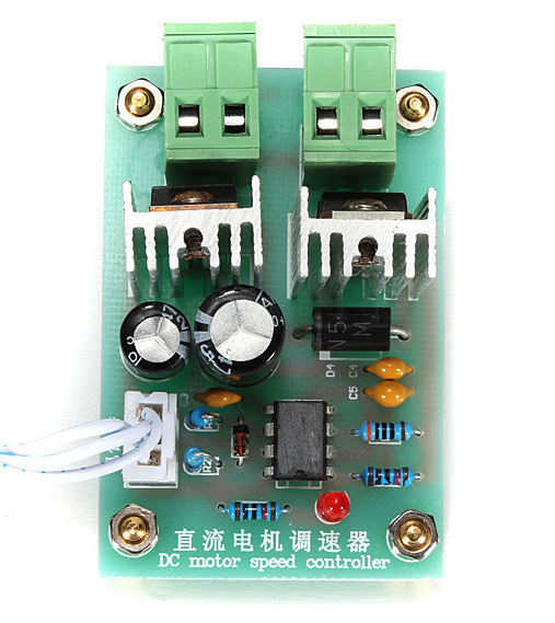
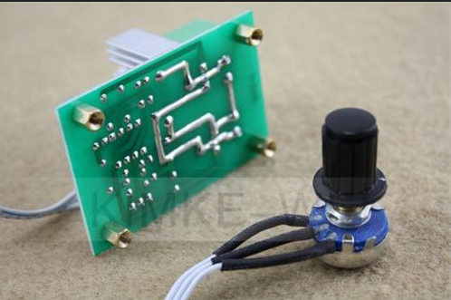
hey y'all. I (unfortunately) bought pwm controller from eBay and there is no schematic on the intrent, And I wanna add to this controller a "kick start"
kick start : https://www.overclockers.com/forums/showpost.php?p=6931080&postcount=822
https://www.overclockers.com/forums/showpost.php?p=7116335&postcount=1214
So, I dont have schematics or anythingfor the contoller I bought so I need a circuit Separate from the controller, a circuit I could add Additionally to the pwm controller.
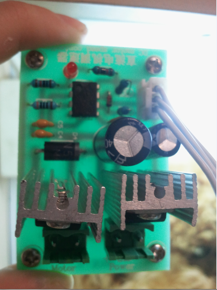
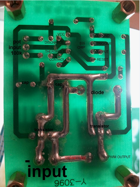
I might could try to make the schematics just by looking at the connections..
 
Last edited:

It could be a simple as fitting a capacitor across the speed control voltage but without schematics it's impossible for us to confirm that.

A good starting point is to look at part numbers in the PWM controller. The gadgets on Ebay are usually as simple as they can be so they use the schematic provided on the parts manufacturers data sheets. If you can identify some of the parts, even if there is no 'official' schematic it will give clues about how to modify it.

Brian.

They made it so You have to desolder the inputs to see the mosfets \ transistors..
expect the mosfets or transistors there are :
IN5 something big schottky diode.
555NE timer
Zener Diode
2 470uF electrolytic capacitors
2 non polrazied small capaictors in series.
1 non polrazied small capaictor
couple of resistors and potentiometer.
dc23d3affa7c99b5fea392cfcf95aa52.png

96799845e88f7fff5d4a6c991f25521d.png
 
Last edited:

Looks like a simple NE555 oscillator with the control adjusting the charge and discharge current ratio. There is a good explanation of how it works here:
https://www.instructables.com/id/555-Timer/step7/555-Timer-Astable-Mode-Duty-Cycle/

If I'm right, the potentiomter is used as both RA and RB so as one increases in value the other decreases. It looks like there are some fixed resistors in series to prevent the value being reduced to zero (short circuited). Unfortunately, this means there are alternating signals on both sides of the potentiometer so a simple capacitor to momentarily 'pull' the control one way will not work.

It should still be possible to do but the method depends on how the output transistor is connected. If you can trace a schematic from pin 3 of the IC to the motor connector it would help greatly.

Brian.
9787ef1c007274753554a8f654b615f1.png

9393be70a40bb1d174837aebfe7e1a57.png


helps?
 

Thanks, that helps.

In the lower photograph the 'transistor' on the left (behind the power input connector) is actually a voltage regulator, probably type 7812 and the one on the right is an NPN power transistor or possibly a power MOSFET.

The schematic is as I expected and described in the link in my previous message. Unfortunatley the NE555 doesn't lend itself to easy control of the PWM by applying a voltage, it needs the component values around it to change, hence the potentiometer. There is a trick you can try though and it doesn't need any modification to the board at all. You need diode (1N4001 through 1N4007 will work) a 10K resistor and another capacitor. The capacitor value depends on the power requirenment of the fan which I have no information about but I would suggest 470uF as a starting value for experiments. Increasing the value will give a bigger 'kick' to the fan when the power is turned on.

Wire it like this:

The cathode of the diode (banded end) goes to the positive end of the new capacitor. The anode end of the diode goes to the PWM output connection, the one nearest the mounting screw in the corner of the board. The negative end of the capacitor goes to the negative supply input connection. The 10K resistor is wired across the capacitor.

This is how it works: When power is first applied the capacitor will be discharged and will draw current through the fan and new diode until it has charged up to supply voltage. This extra burst of current is what 'kick starts' the fan. The diode prevents the new capacitor discharging back into the PWM transistor when it conducts so the process isn't continuously repeated. The new resistor is there to slowly discharge the capacitor so it can produce a fresh kick start after a few seconds of the power being removed and reapplied.

Try it and see.

Brian.
How do i wire the fan?

I use fan model PFC1212DE. it draw 4.80A at the start.
 
Last edited:

The fan connects across the 'motor' pins on the board.

The 'kick start' diode and capacitor connect between the positive supply to the board and the positive side of the fan.

Looking at the data sheet it appears there are several version of this fan. If you have the type with red/black/blue and yellow wires the control board you have is not suitable. On those versions the controller is built into the fan itself and all you have to do is provide a low power PWM signal.

Brian.
I do have the version with the 4 wires, PFC1212DE-6A50.
But how can my control board not suitable? It works great. But I dont connect the pwm wire to the pwm, I just connect the + to the + and - to the - and I know its not supposd to be like that but it works.
somebody else told me to do that :
c0a7a35ef13bbab73e90dddc15ec7036.png
 

Then what you are doing is let it's internal controller run at full power and use your board to limit the power externally. You have two PWM controllers in series with the second (internal) one running at 100% all the time. It works but it isn't very efficient and it makes the kick start trickier to predict.

The proper way to control it is to use the frequency output wire from the fan to let the control board know how fast it is rotating and compare that to the speed you want it to run. That method lets the controller provide the kick start itself then automatically back off the power when the frequency output indicates rotation has started. The circuitry is more complicated and ideally would use a microcontroller but it also gives prcise speed control and start up.

Brian.
 

Status
Not open for further replies.

Part and Inventory Search

Welcome to EDABoard.com

Sponsor

Back
Top