jabbar81
Newbie level 4
- Joined
- Mar 27, 2006
- Messages
- 7
- Helped
- 0
- Reputation
- 0
- Reaction score
- 0
- Trophy points
- 1,281
- Location
- Seoul, Korea
- Activity points
- 1,371
I am designing a DC-DC converter for impedance matching of my piezoelectric energy harvester with flyback converter. The switching frequency of the dc-dc converter is about 1kHz. The voltage is around 20V and current is about 2mA.
I made a transformer using EPCOS EFD 20/10/17 B66417U0160K187 core with air gap. It has one primary and two output windings. One output (secondary-1) winding is used to power the wireless sensor. Second output (secondary-2) is used for oscillator (switching for MOSFET) and start-up circuit.
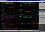
I took the data using the Agilent Impedance Analyzer. In the attached figure, the input impedance, inductance are measured from 100Hz to 4kHz.
Then new lines were plot by shorting both the output winding. Equivalent circuit values are also shown.
I want to know, can anyone told me how bad I wound my transformer? Is it possible to measure leakage inductance from these graphs?
Kind Regards
Hamid
Hanyang University
Korea
I made a transformer using EPCOS EFD 20/10/17 B66417U0160K187 core with air gap. It has one primary and two output windings. One output (secondary-1) winding is used to power the wireless sensor. Second output (secondary-2) is used for oscillator (switching for MOSFET) and start-up circuit.
I took the data using the Agilent Impedance Analyzer. In the attached figure, the input impedance, inductance are measured from 100Hz to 4kHz.
Then new lines were plot by shorting both the output winding. Equivalent circuit values are also shown.
I want to know, can anyone told me how bad I wound my transformer? Is it possible to measure leakage inductance from these graphs?
Kind Regards
Hamid
Hanyang University
Korea
Attachments
Last edited: