Continue to Site

Welcome to EDAboard.com

Welcome to our site! EDAboard.com is an international Electronics Discussion Forum focused on EDA software, circuits, schematics, books, theory, papers, asic, pld, 8051, DSP, Network, RF, Analog Design, PCB, Service Manuals... and a whole lot more! To participate you need to register. Registration is free. Click here to register now.

My crystal radio circuit isn't working

Status
Not open for further replies.

Resistanceisfutile

Member level 4
Joined
Aug 22, 2012
Messages
77
Helped
2
Reputation
4
Reaction score
1
Trophy points
1,288
Activity points
2,008
Hi how you doing!
I've been trying to build a crystal radio based on designs I found on the internet.
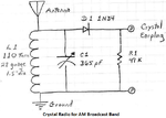
I built the crystal radio circuit that I found on the internet, but I've had no luck getting it to work. I've attached a photo of the circuit diagram and the circuit I've built (apologies, it is very flimsy).

My components are: a 0.001 uF capacitor and an inductor I calculated to be about 0.16 uH (these form the tuning circuit I'm guessing), a crystal earpiece from an old crystal radio set (so I'm guessing they are the right impedance) and an 0A90 (10mA signal diode). My antenna is simply a wire and my ground is just a lead to a metal lid.

Based on my resonant frequency calculations, the circuit should be tuned to 12.5 MHz and I've been told that if my crystal earpiece is working I'll get static (so even if it is an empty station, I should be getting static right? Can someone confirm this?)

However, I get nothing out of the earphone. Can anyone tell me what I might be doing wrong and how I could solve it?

CircuitDiagram.png
classic crystal radio 2.jpg
 

The detector diode does not have a load because crystal earphones do not conduct electricity. All the crystal radios on the internet have a 47k resistor as a detector load in parallel with the crystal earphones.
12.5MHz is shortwave. The coil is usually 10 to 20 turns on a ferrite core (your air-core coil is for 80MHz) and the capacitor in parallel with it should be 100pF to 400pF, not 0.001uF which is 1000pF.

You need an insulated antenna the correct length up high and an earth ground.
I have never played with shortwave so I do not know if anything is on 12.5MHz.

How do you know if the headphones work and are crystal? Use an ohm-meter, they should be infinity ohms and make a click when the probes touch the two wires.
 

The incoming signal needs to reach a greater voltage than the diode threshold. Have you listened when a lightning storm is within, say, 30 miles? That's when you will get loud static clicks.

Or, create your own static with this technique I saw in a Forrest Mims book. Connect a wire and a file to opposite terminals of a 1.5V battery. Scratch the wire across the file, creating sparks. This will broadcast loud static on every radio frequency.
 

Ground does not mean the tin lid!! Ground means a spike into the earth. (if you are very careful you can use the mains earth but I did not say this) With a fixed capacitor value you are unlikely to pick up any stations. You can test that the crystal set is basically working by touching your finger on the diode where it joins with the earphones. When you do this you should hear a buzz. I think that for your first crystal set you should build one for the medium wave and then try short wave.
 

Not a chance of working!

why?
1: the ground should be real ground - preferably a rod driven into real Earth beneath your feet.
2: the tuning components are wildly inappropriate. Get a tuning (adjustable) capacitor and make to coil about 75 turns so it covers a lower frequency where you should find stong stations. Just aiming in the dark for a frequency that may have nothing on it will never work!
3: add a resistor of about 10K across the earphone. The value isn't critical, anything from about 4.7K to 47K will work equally well.
4: the antenna wire should be > 4m long, for lower frequencies you ideally want one about 50m long!

Brian.
1) That is what I said, and is probably the main reason the crystal set is not working at all
2) I have found that shortwave crystal sets were hard to get working, start with a medium wave one.
3) You don't need the 10K resistor across the headphones, but depending on the headphones type a 10K resistor may reduce distortion.
4) You could not see the length of the antenna in the picture, but the longer the better. However if you have a good earth this is less important.
 

3) You don't need the 10K resistor across the headphones, but depending on the headphones type a 10K resistor may reduce distortion.
Maybe you are thinking about high impedance (2k ohms) dynamic headphones? These ones are crystal (piezo?) which prevent the detector diode from doing anything since it has no load.
 

Attachments

  • crystal radio.png
    crystal radio.png
    143.4 KB · Views: 194

Audioguru, it actually WILL work without a load resistance but might be distorted because the capacitance of the earpiece causes it to develop a DC voltage across it and that makes it only respond to peaks of modulation higher than that DC. In practice, the source current from the diode is likely to be in uA at best so the leakage resistance back through the diode and the earpiece can easily discharge it without a resistor assisting. Technically, it should also have a capacitor after the diode to filter out the residual RF but again it is seldom required.

Brian.
 

The circuit will not work on alligator clips.
The coil has to have the correct number of turns and the capacitor has to be close to the coil to produce a TUNED CIRCUIT.
The tuned circuit resonates at the frequency you want to pick up and produces a voltage 100 times higher than the signal it is receiving.
The signal is now large enough to pass through the diode and gradually charge the capacitor (inside the earpiece). When the pulses are not quite as strong, the capacitor discharges via the resistor across it. The capacitor inside the earpiece is also a crystal that expands when it receives a voltage and it is connected to a very thin diaphragm of aluminium.
The end result is the diaphragm vibrates to produce the audio.
 

Personally I'd recalculate for another frequency, I can't hear anything on 12.5mhz.

Perhaps around 7.3 will provide some commercial stations to listen to.

And good luck with getting it going, now your on a slippery slope to other radios :)
 

"now your on a slippery slope to other radios"

Whys is it so DANGEROUS going to other radios???
 

Simple cheap radio circuits use very slippery "slope detection" to receive distorted FM transmissions. Then the circuit might fall down which is dangerous.:laugh:
 

Hi all
I remember when i was a little boy , it was one of the most interesting and simplest radios which i built . it worked fine . i still have that radio and this topic caused that i have a look into my storage and i found it again ! it still works ha ha !
How it works :
Use a very long wire as aerial . or perhaps use a wire and tie it into the telephone plug and tie the other side of the wire into the tuning circuit . make sure the crystal earphone is still intact . ( which i think it is because their lives won't be finished simply ! )
And use an MW coil as your inductor , which is twisted on a ferrite core . and use an MW variable capacitor . ( you can buy them or take them from old radios )
Now test it , it will work as well !
My crystal earphone is like what physicians using ! it has both R and L side but in that shape ! it is spectacular ! ha ha

Good Luck
Goldsmith
 

Goldsmith,
Maybe in your country you do not have hundreds of radio stations in every direction like we have here. Then the single tuned circuit in a crystal radio causes very poor selectivity and you hear a few radio stations at the same time.
80 years ago when crystal radios were popular there were few radio stations so poor selectivity did not matter.

How many tuned circuits are there in a cheap AM radio? 5 or 6?
Hi Buddy !
No , here there are a lot of radio stations which is impossible to hear them all , because they are too many and who has time for all of em ?
I know you are familiar with TRF radios , some of them are just using a single stage tuned circuit as input ! ( a transformer and a variable capacitor and some trimmer capacitors ) and an RFC it works perfectly fine . ( it is important how to design ! ) i use a narrow band aerial tuning circuit of course but for my crystal radio it works fine how ever i can hear a weak signal of the other stations too but it is weak .

About detector cheeps i must say they use a lot of tuned stages which makes them pretty narrow band .

Regards
Goldsmith
 

Status
Not open for further replies.

Similar threads

Part and Inventory Search

Welcome to EDABoard.com

Sponsor

Back
Top