Continue to Site

Welcome to EDAboard.com

Welcome to our site! EDAboard.com is an international Electronics Discussion Forum focused on EDA software, circuits, schematics, books, theory, papers, asic, pld, 8051, DSP, Network, RF, Analog Design, PCB, Service Manuals... and a whole lot more! To participate you need to register. Registration is free. Click here to register now.

[General] Design problem with 74HC595 IC in proteus

Status
Not open for further replies.

biswajitdas49

Member level 3
Joined
May 17, 2012
Messages
55
Helped
0
Reputation
0
Reaction score
0
Trophy points
1,286
Location
WEST BENGAL,INDIA
Activity points
1,726
HELLO EVERYBODY,
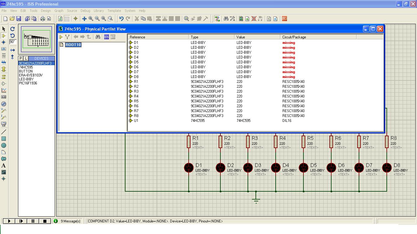
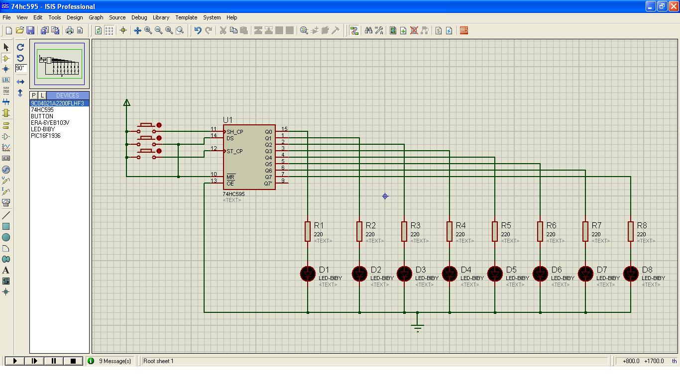
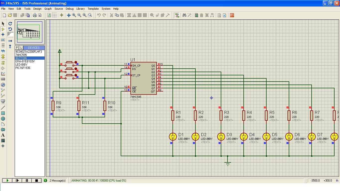
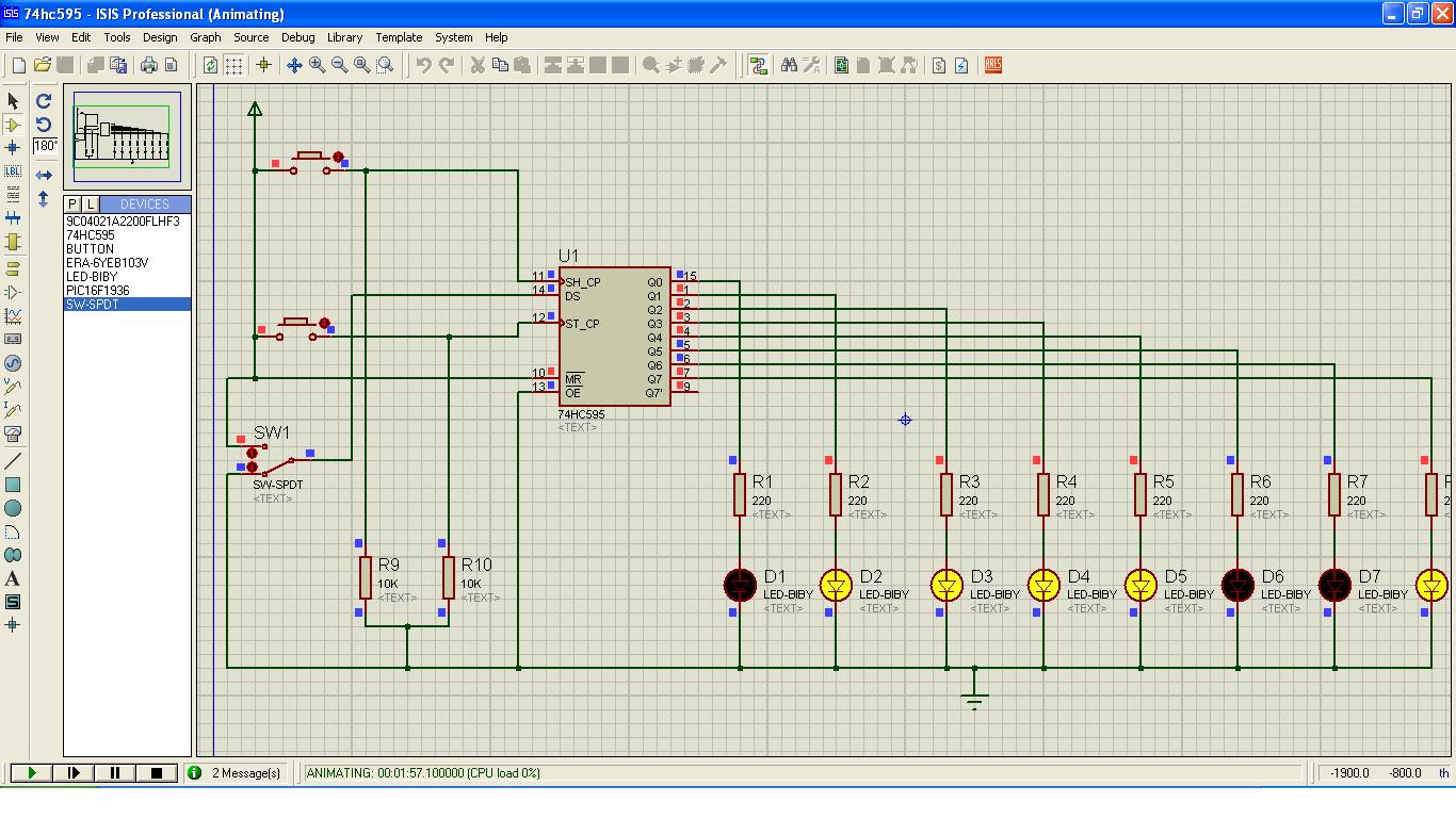
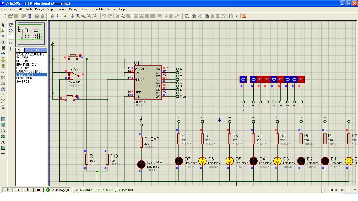
I want simply simulate the IC 74HC595 in proteus 7.8 sp2.So design it with push buttons and some leds,but when I simulate it none of the led will glow.I find something missing like error massage in design explorer.what is the fault in my design?

because perfectly simulate I connect a PIC mcu with 74hc595.
here is the picture:-


The outputs go LOW when active so the LEDs have to be connected to the positive 5v.
 

Several points to note --

1) your pin's 11 & 12 are not properly managed. When your switch is closed it is pulled high, but when it is open they are floating - which is usually taken a High. So basically you are never providing any clock pulse at all. Fix this and you should have the LEDS lighting with each pulse.
2) your Data-in pin is permanently high. Nothing wrong with that, just pointing it out.
3) Ignore colin55's advise, it is meaningless.
 

You need to add pulldown resistors to the signal side of the pushbuttons.

@Colin
The data input is wired to Vcc, so it will never go low. The outputs may start low though.
 

THANK YOU KRIPACHARYA, your suggestion help me to see the o/p. but is there any solutions,which help me to show high and low output at the same time, bcoz it show me only high output due to data pin always pulled up.Now if I want to show zero in any o/p pin then what will be the configuration.Please suggest me.

here is the schematic with o/p:
 

You have to shift 8 bits of data and then make it appear at the 595's output. If you want LED2 to be 0 then shift 0b11111101 and then load it to output.
 

SORRY EVERYBODY, after some googling I found that, in proteus there is a SPDT switch, which is always on or off.which help me to do my desired o/p.

here is my new design with this spdt sw:


Hi,

in simulation this works, but not in reality.

You have to add some debouncing to your inputs.

Maybe a 10nF C will do.


Klaus
 

Hi,

in simulation this works, but not in reality.

You have to add some debouncing to your inputs.

Maybe a 10nF C will do.


Klaus

That's true of course, and in fact many other things need to be done for a real-world implementation.

But I quote the OP... "I want simply simulate the IC 74HC595 in proteus"
 

That's right kripacharya, actually I faced a problem that is, data pin input, because that time I use only a push button for data pin and when I pressed the PB, the CLK pin was low thats why I didn't get any output. But we know 74hc595 is a latched D-flipflop and D-FF give o/p high when it's D pin & CLK pin is high at a same time. then I solve it by using SPDT Switch which is stayed always high or low,I also find another tool named LOGICSTATE in proteus, which is same as switch.

Now its work fine!!!!!

HERE IS THE FINAL CIRCUIT-


THANK YOU EVERYBODY FOR SUGGESTION!!!!!!!!!!!!
 

You can use LogiCc state or Logic Toggle part in Proteus.
 

Status
Not open for further replies.

Similar threads

Part and Inventory Search

Welcome to EDABoard.com

Sponsor

Back
Top