Continue to Site

Welcome to EDAboard.com

Welcome to our site! EDAboard.com is an international Electronics Discussion Forum focused on EDA software, circuits, schematics, books, theory, papers, asic, pld, 8051, DSP, Network, RF, Analog Design, PCB, Service Manuals... and a whole lot more! To participate you need to register. Registration is free. Click here to register now.

Signal from strain gauge amplifier

Status
Not open for further replies.

PYGuj

Junior Member level 1
Joined
Jul 22, 2014
Messages
18
Helped
0
Reputation
0
Reaction score
0
Trophy points
1
Activity points
132
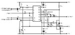
Hello! i am using the attached strain gauge amplifier circuit for my project. i am unable to have the output at zero under no-strain condition. I am trying to adjust the trimmers VR1 and VR2 for this purpose but to no avail. As a result i am having negative values which is not at all what i require. Also i need to feed the output signal of the amplifier to a microcontroller but the signal fluctuates too much. Can anyone please help me through the circuit and for processing the signal from the amplifier? Thanks!
 

Attachments

  • Untitled.jpg
    Untitled.jpg
    93.2 KB · Views: 92

It would be helpful to have part numbers, and/or component values, in the schematic - I cannot tell what that IC is supposed to be?
 

Thanks for the reply. I indeed forgot to include the values. the IC is the strain gauge amplifier and the circuit around is for reducing noise, drift etc and also to adjust the bridge initially to zero for bridge imbalance but the latter function is not working (or maybe i am not able to do it). The component values are as followed. Please advise me on how to eliminate the imbalance since this is not allowing me to move further in my work.
R1, R3=100k
R2, R6=100R
R4=68R
R5,R8=10R
R7=47R
R9=1K
T1:BD135
T2:BD136
T3:BC108
C2,C5:10nF
C3,C4:10uF
C1,C6,C7:100nF
D1,D2:1N823
 

IF the IC is a commercially available product, it would be most helpful for you to tell us the part number, manufacturer so that we could reference the datasheets.
What circuits/methods and voltage levels are powering the IC. If it is not tightly regulated, depending on the amplifier configuration it may not be rejecting all the ripple in the P.S lines.
Are you using 1% or better tolerance resistors with low tempco ?
Can you post a pic of scope trace showing the problem(s) you have?
 

I think you are using the RS 846-171 24 pin DIL strain gauge amplifier. The data-sheet states that R3 and R4 may by adjusted to alter the zero adjustment range. It could be your range is too narrow to compensate for the actual imbalance of your gauge. Did you build by yourself the strain-gauge ? In this case it could be some of the gauges is stressed even if zero strain is applied.
 

Hi..i am indeed using the RS 846-171 24 pin DIL amplifier and i am using all the recommended components in the datasheet. yes i have myself built a half wheatstone bridge which i am using for testing purposes for bending strain. how do i know the range of R3 and R4 i will require? I have followed the instructions for building the bridge though i acknowledge that i do lack expertise to do so. this amplifier is only part of my project and i am not very conversant with instrumentation amplifiers.
 

Hi,

Edit:Sorry i deleted my unappropriate post.

Klaus
 

Status
Not open for further replies.

Part and Inventory Search

Welcome to EDABoard.com

Sponsor

Back
Top