steve_rb
Full Member level 3
Hi everyone
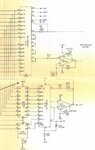
Attached is output section of a digital to analog circuit. It is supposed to give 0-10 V at the output as reference voltage. Potentiometers are supposed to adjust the output exactly in this range but non of them not affecting the output at all. I am not good in electronic circuits and need help with this. First of all I need to know how this output section is functioning and secondly why potentiometers have no effect on the output? If they should what might be the problem to consider first?
Steve