Continue to Site

Welcome to EDAboard.com

Welcome to our site! EDAboard.com is an international Electronics Discussion Forum focused on EDA software, circuits, schematics, books, theory, papers, asic, pld, 8051, DSP, Network, RF, Analog Design, PCB, Service Manuals... and a whole lot more! To participate you need to register. Registration is free. Click here to register now.

NE555 Turn signal... would that work? :)

Status
Not open for further replies.

MrPopples

Newbie level 5
Joined
Jul 20, 2014
Messages
10
Helped
3
Reputation
6
Reaction score
3
Trophy points
3
Activity points
128
Hello there :D

I'm trying to remember how to do "basic" electronics and the first small project I'm on is my bike turn signal ... based on the famous NE555.

ok, there's plenty of examples with NE555 ... and I shouldn't have screwed that part ... but I haven't done electronics in nearly 10 years ... I'm only programming stuff nowadays ... 8-O

so, I've made that little schematic ... and I have one question ... would that work?
rXUlbXN.png


I'm not sure I need R3 here ... it's been a long time since I've played with FET 8-O
I need to drive around 40 watts of blinking madness with a duty cycle of 50% (hence the diode on R2)
I didn't really thought about what would be the frequency I want ... this setup gets me roughly 0.7Hz which should be close to good.

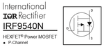
I've chosen a the IRF9540N for it's fair price and its low RDSon.
I calculated roughly 1W of power loss in the FET while ON ... which should be low enough :)
putting a mechanical relay is a 'no-go' since the bike vibrates way too much (it's a Buell btw).

I could buy a turn signal for $10 ... but I had 2 die on me ... and that's enough ... :)
well, I guess it's not a bad start? :)
 

It should work - as long as you connect the lamp in the drain of the MOSFET. The results will be unpredictable if you put it in the supply to the 555 as well because it's voltage will be dropped by the lamp and it might reset or get 'stuck'.

You don't need R3 and you can probably remove R6 as well.

Brian.

That circuit will not work
 

An explanation would be useful Colin!

What you really need is a two terminal oscillator. When I did this on a motorcycle I simply used a high current changeover relay with the NO contact in series with the lamps and the NC in series with the coil. So when turned on, the coil energized, turned the lights on and itself off. A large capacitor across the coil slowed the operation down. That was maybe 30 years ago, in hindsight and with modern components it could be done with a MOSFET driver and smaller capacitor.

Brian.

(and thank you Colin for not including any of my designs in your hall of shame on your web site!)

Brian, - I don't know you.

The circuit will not work. By the time you try to put 12v across the 3R5 you have the MOSFET sitting up in the air, how do you expect to provide added voltage to turn it ON via the gate !!!!!!!!!!!!!!!

No-one has picked out the absurdity of the circuit.
 

@MrPopples

You have not added a lamp in the schematic, but I have a hunch that R6 is supposed to be the load because it is almost 40W@12v, is this the case?
If it is and both the supply of the 555 and the mosfet are the same level then it will not work, unless you move the load to the other side of the mosfet, between the drain and positive supply (mosfet as low side switch).

Another alternative is to feed the mosfet drain with a lower voltage e.g. 6v (while the 555 still uses 12v) in which case the circuit will work as is with the load in the source side (high side switch)
 

thank you all for your responses :)

It should work - as long as you connect the lamp in the drain of the MOSFET. The results will be unpredictable if you put it in the supply to the 555 as well because it's voltage will be dropped by the lamp and it might reset or get 'stuck'.

You don't need R3 and you can probably remove R6 as well.

Brian.

Ok for R3.
R6 actually is my load as Alexan pointed out.

I cannot move the load anywhere else, I'll try to remake the schematic to show where the module I'm making connects with the whole thing.
The lamps are tied to the ground and I have to provide them 12V ... so I'm stuck with a high side switch.


@MrPopples

You have not added a lamp in the schematic, but I have a hunch that R6 is supposed to be the load because it is almost 40W@12v, is this the case?
If it is and both the supply of the 555 and the mosfet are the same level then it will not work, unless you move the load to the other side of the mosfet, between the drain and positive supply (mosfet as low side switch).

Another alternative is to feed the mosfet drain with a lower voltage e.g. 6v (while the 555 still uses 12v) in which case the circuit will work as is with the load in the source side (high side switch)

I now understand the issues with Vgs and the source "floating" while the lamp is not powered on. I'm not sure I get the full picture but that's a start ... :D
I'd like to keep my lamps and NE555 under 12V as the form factor for this should be quite small and I have no other voltage available.

I'm really more at ease with NPN/PNP transistors ... but that's the point here, getting back at doing electronic stuff and learning :)
 

When you use a N-mosfet as a high side switch (load connected at the mosfet source) and try to drive the mosfet gate with the same voltage level as the drain, then as the mosfet turns on, the voltage at the source increases which in turn decreases the Vgs. This leads in a half open state which overheats the mosfet, so you either need to drive the gate with a voltage higher than the one connected at the drain or you need an isolated voltage source that can be applied between the gate and source.
 
Nobody noticed that the IRF9540 very old Mosfet is P-channel, is drawn with a wrong symbol on the schematic and is upside down.
 

Attachments

  • IRF9540 Mosfet.png
    IRF9540 Mosfet.png
    13.8 KB · Views: 142

Well spotted Audioguru but I think the intention was understood even if the symbol was wrong.

Colin, you are quite right about the voltage drop across the resistor lifting the source voltage, which is why I suggested it should be removed, it wasn't at all obvious this was intended to represent the lamp in the real application.

What is needed is a solid state two terminal oscillator, one that turns it's own current off periodically and is a 'drop in' replacement for a mechanical 'winker' unit. It is an interesting challenge. There is a design at:
https://www.brighthubengineering.co...this-heavy-duty-flasher-unit-in-your-mo-bike/
which is drawn to be confusing but could be the basis of the better design. The one shown is certainly pushing the components to the limit when you consider most 12V lamps draw around 2A.

I'm completely without my lab at the moment, all I have is a laptop in a single room apartment and I'm spending all day on at the site rebuilding the new place myself so any experimentation is out of the question. My first thoughts though are to see if it's possible to use an SCR as the switch and commutate it to turn it off.

Brian.
 

The OP posted a circuit using an N-channel Mosfet as a source-follower that he calls a "high side switch". With a 12V supply then the output of the 555 is about +10.5V but the gate of the Mosfet needs +22V to fully turn on.

The schematic should be corrected showing a P-channel Mosfet as a common source driver not as a source-follower.
 

The important pont is that you can't easily connect the load in the drain or source side, it has to be in series with the whole supply. In other words the unit has to work as a series switch being turned on and off periodically and has only two wires to it. Whether it has to be 'high side' or 'low side' is decide dby existing connection to the load and in this instance the lamps are almost certainly conncted to chassis on one side, forcing it to be in the 'high' side of the supply.

Brian.
Thank you, Brian.
That explains why the original schematic had the Mosfet shorting the supply voltage if it ever turned on.
 

Thanks for all the comments.
I think I didn't understand why I needed 22Volts to drive the FET ... but I'll work on that :)
gonna document myself :)

What is needed is a solid state two terminal oscillator, one that turns it's own current off periodically and is a 'drop in' replacement for a mechanical 'winker' unit. It is an interesting challenge. There is a design at:
https://www.brighthubengineering.co...this-heavy-duty-flasher-unit-in-your-mo-bike/
which is drawn to be confusing but could be the basis of the better design. The one shown is certainly pushing the components to the limit when you consider most 12V lamps draw around 2A.
Brian.

I have seen some of these "astable multivibrator" variants, and they all seem to use the load as part of the multivibrator setup (didn't look too closely at the schematic your provide).
What I intended to do here, is have a schematic that would work at the same frequency, whatever the load.
The load could be lamps and draw 40W or could be LEDs and draw only 5W ... or I could have LEDs for the front turn signal and lamps for the rear turn signal.

I've spotted on the schematics at work that we use some TPS22930A ... and I wonder if the same component with the good voltage/wattage rating would be a direct replacement of the FET in my "original design"

Nobody noticed that the IRF9540 very old Mosfet is P-channel, is drawn with a wrong symbol on the schematic and is upside down.

well, good catch, I nearly bought some irf9540n ... :)
PS: I'm running under linux, using gschem ... and I'm not sure of what I'm doing with it ...

all in all, I need to take some time to think about all that :)
 

I think I didn't understand why I needed 22Volts to drive the FET
You had an N-channel Mosfet connected as a source-follower. The drain was connected to +12V and the load was connected to its source pin. You want its source pin to go to +12V when it is turned on.
The datasheet for most N-channel Mosfets show that they are fully turned on when the gate-source voltage is 10V.
If the output of the 555 was able to go high to +12V then the gate of the Mosfet would be +12V and its gate-source voltage is ZERO if you want the load to be turned on at +12V. So for the source pin to be near +12V its gate pin must be 12V + 10V= +22V which is impossible in your circuit.

A P-channel Mosfet can be a high side switch when its source is connected to +12V and the load is connected from its drain pin to ground. When its gate is near +12V then the gate-source voltage is low so it is turned off. When its gate voltage is near ground then it has 10V or a little more gate-source voltage so it is fully turned on.

The datasheet for the TPS22930A shows that it is a P-channel Mosfet with a logic circuit at its input. Its logic input voltages are about +5V and ground. Its maximum allowed current is only 2A.
 
Hey guys ...

sorry for the lack of news.
If you must know, I'm currently buying a house... and it takes a lot of my spare time with those awful banks :-/

I didn't forget the project ... and the more I think about it, the more I'm thinking the 'solid state two terminal oscillator' solution proposed by betwixt is the right solution.
I just need to figure out how to make it "load independant" as I want to be able to plug lamps or LEDs to it without any (or, let's say slight) variation of the oscillating frequency.

the NE555 approach seems complicated because I don't want to 555 to keep oscillating when I'm not using my turn signals.
there's the RESET pin on the 555, but the spec says there's a chance the output might stay at the state it was when toggling RESET... or am I wrong?

Thx guys,
This project _will_ happen ... I just don't know when :p
 

A 555 draws only a tiny current when oscillating so that shouldn't be a problem. You are right though, some 555 versions reset high, some low and some just freeze at their state when reset is applied. This may contradict what some data sheets say, I know the truth from experience!

Your problem is still only having two wires, one in and one out. What you need is a periodic switch that requires no other power source but cyclically (no pun intended) connects and disconnects the in and out wires.

Is it safe to make these assumptions?
1. One side of the lights is connected to chassis (they only have a feed wire to them)
2. The chassis is connected to the negative side of the battery
3. You want to avoid adding extra (permanently 'live') wiring back to the battery. In other words, only use the existing two wires.

It would also help if you could tell us the voltage it has to run on (battery voltage) and the power rating of the lamps. I am guessing there are two lamps in parallel on each side so we need the combined rating of both.

If you think buying a house is a problem, pity me, I'm actually building one!

Brian.
 

I will remake a new schematic which shows the actual connections of everything :)

I have the chance to have a bike that use a "3 pin connector" for the "winker unit", so I actually have +12V/GND and +12V for the lamps/leds.

Is it safe to make these assumptions?
1. One side of the lights is connected to chassis (they only have a feed wire to them)
2. The chassis is connected to the negative side of the battery
3. You want to avoid adding extra (permanently 'live') wiring back to the battery. In other words, only use the existing two wires.

1. Yes, the lamps are connected to the chassis. I could "unplug" them pretty easily, I'll just have to re-wire everything ... so that's not an option ... until I change my mind :)
2. Yes, AFAIK, only some old ancient cars from UK had the chassis connected to the positive side of the battery
3. The good news is: the original winker unit has 3 wire, including a permanent +12/GND :)

I'll get the rating of the lamps, but I'm roughly guessing each lamp is around 15W
everything should be clearer with a better schematic :)

I know that the 555 won't consume much current ... but I in terms of "aesthetics", It's regrettable to keep it running when not needed ... well, I could live with it I guess.
I program embedded stuff for a living. We try to stop everything as soon as it's not needed (clocks, voltage rails, gpios ...) that's kind of an habit now :)

We wanted to build a house ... doing everything from scratch ... and we decided we didn't want to wait so long before moving. Mainly because of the noisy neighborhood.
I wish you good luck with your house :)
 

Ok, I will stop changing my mind and just go for it.

so, according to all reviews and opinions ... this would work:

cwm9mip.png


I add the 3 test points LSPN to show where my module attaches. it should be clearer.

I still need to choose Q1... which should be an issue of "what's available for cheap on fleabay?".
with around 2 amps per lamp, that's max 8 amps *if* I modify the switch to have a "warning" (aka: all turn signals on).
I'll see if I can find a FET that can handle 8 amps ... if not I'll settle for the regular "right" XOR "left" switch.

btw, I plan later to use LEDs instead of lamps... but I need to be able to switch to lamps if the cops gets angry ...
I understand it shouldn't be a problem with a FETs as they are "voltage driven" (as opposite to BJT).
 

An LED needs a current-limiting resistor in series with it or a few low voltage LEDs can be connected in series with a series current-limiting resistor.
 

Status
Not open for further replies.

Similar threads

Part and Inventory Search

Welcome to EDABoard.com

Sponsor

Back
Top