Continue to Site

Welcome to EDAboard.com

Welcome to our site! EDAboard.com is an international Electronics Discussion Forum focused on EDA software, circuits, schematics, books, theory, papers, asic, pld, 8051, DSP, Network, RF, Analog Design, PCB, Service Manuals... and a whole lot more! To participate you need to register. Registration is free. Click here to register now.

Can we get super high SNR by performing ICA on every single patch of antenna?

Status
Not open for further replies.

Terminator3

Advanced Member level 3
Joined
Feb 25, 2012
Messages
802
Helped
71
Reputation
142
Reaction score
63
Trophy points
1,308
Activity points
9,027
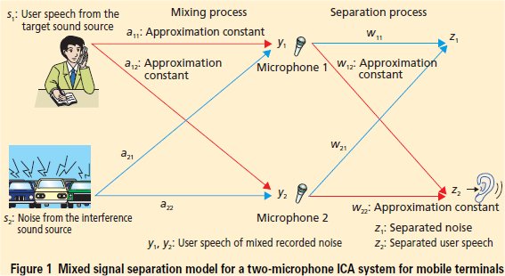
There is an interesting thing called ICA (independent component analysis).
What if we make patch array antenna, put capacitor on each patch feeding and schottky diode. In this way we can get separate DC signal from every single patch, as self-mixing occurs in patch. Then next step is to wire all this DC outputs to modern ARM (stm32, nxp, etc..) with multiple ADC inputs, and perform ICA analysis. If you google on ICA for microphone arrays, it may be feasible. Super performance receiving signals with huge interference. Patch signals does not require to be in-phase, as we perform ICA. It is well known and studied on microphone arrays, etc. Bad thing is there is no gain for single patch, but it can be solved by making array of arrays.

Idea behind this is to overcome SNR vs DIRECTIVITY problem, huge interference problem, poor performance problem. If we make array too large, then beam will too narrow, and in many applications impossible to align beam of TX/RX systems. Some interference make impossible to work in traditional way. Some systems have too poor performance, and improving arises cost problem.

For example, 3x3 patch array, 9 patches, 9 schottky diodes, 9 capacitors for DC block, 9 capacitors for low frequency AC, some cheap Cortex microprocessor with 9 ADC channels (single ADC multiple channels). DSP using ICA method.
 

I think the analogy to audio is misleading. In your example, you would need to sample the RF signal and evaluate the RF differential phase data for "post-processed beamforming". In your example with detectors, there is no phase information available, so no way you could differentiate between signal from different angles.
 
I explained not very well. Idea is not to make any beamforming. Idea is to separate received signal from noise and unwanted interference signals.
As in case with audio microphones: ICA microphone array separates different sound sources, but do not give any direction.
So this patch array do the same, separate different signal sources, but do not give any direction information.

I can imagine some array of monopoles hand held radio... with ICA processing.
 

I explained not very well. Idea is not to make any beamforming.

I understood that.

Idea is to separate received signal from noise and unwanted interference signals.

Right. You might not realize it, but in your audio example, this is done by digital beamforming. That's the trick. And you need phase information for that.

- - - Updated - - -

Another way to think about it:

The requirement for ICA analysis as descriped at Wikipedia is that you have independent signals, where independent is defined like this:
Code:
"The two broadest definitions of independence for ICA are
    Minimization of mutual information
    Maximization of non-Gaussianity"

In your example with the patch array, the piece of information that is different between the signal from different patches would be phase. By using a detector, you loose that RF phase information, and now have many signals that are almost identical. That's not good input data for your ICA method.
 
by RF phase, do you mean high frequency RF phase? But we still have low frequency phase, and also different amplitudes of components. Signal in two antennas may look the same, but it components in sum have different amplitudes. Then ICA can work out those amplitudes. Somehow it must work. I am going to search through papers on internet, maybe there something done before
 

The circuit will work in RF and is in use for many years especially in HF frequencies. For some examples search the net for: "XPhase - Interference reduction "
The main problem of the system, like in any other multi-antenna systems, is that you need good antenna correlation (or isolation between antennas) which sometime is hard to get.
 

The circuit will work in RF and is in use for many years especially in HF frequencies. For some examples search the net for: "XPhase - Interference reduction "

I think this is different from what Terminator3 tries to do. Your XPhase approach is based on adding different signals with RF phase offset. That for sure works.

- - - Updated - - -

by RF phase, do you mean high frequency RF phase?

Yes, correct.

But we still have low frequency phase, and also different amplitudes of components. Signal in two antennas may look the same, but it components in sum have different amplitudes. Then ICA can work out those amplitudes. Somehow it must work. I am going to search through papers on internet, maybe there something done before

Let us know what you find.
 

I think most good laptops have 2 patch antenna with a diversity switch, but many do not. The RSSI signal may indicate Rice Fading {Ricean} from multipath and then switch antenna to improve error rate. Position or orientation sensitivity is often 1 degree or 1 mm makes a huge difference when in a null from -80 to -70 for example . Of course cost increases with more antenna and pin diode switches is a tradeoff.
 

I think that the audio ICA system use at some point also phase cancellation for noise (as XPhase), after mixing and separation process.

From the document from where I took the image below is mentioned:

"the frequency separation signal is reconverted into the time domain to obtain the independent signals in the time domain"

For me this conversion to time domain seems that is necessarily to get the phase cancellation of the noise.


Status
Not open for further replies.

Part and Inventory Search

Welcome to EDABoard.com

Sponsor

Back
Top