Continue to Site

Welcome to EDAboard.com

Welcome to our site! EDAboard.com is an international Electronics Discussion Forum focused on EDA software, circuits, schematics, books, theory, papers, asic, pld, 8051, DSP, Network, RF, Analog Design, PCB, Service Manuals... and a whole lot more! To participate you need to register. Registration is free. Click here to register now.

High Frequency amplifier

Status
Not open for further replies.

Johnny101

Member level 1
Joined
Jul 13, 2014
Messages
34
Helped
0
Reputation
0
Reaction score
0
Trophy points
6
Activity points
356
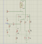
Hello everyone I am trying to built a discrete transistor amplifier using 2N3904 npn transistor. I am trying to achieve a 4Vpp output with 0.7Vpp (Sinusoid) input with a bandwidth of 120 MHz.

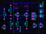
The amplifier that I have designed meets my requirement when simulated in Proteus but when implemented on PCB the gain starts to roll off after 1MHz. Any help would be appreciated.
 

You forgot to post your schematic.
The simulation probably does not include stray capacitance that together with circuit resistors form lowpass filters.
The resistor values need to be fairly low and the currents fairly high to work at the very high frequency.
Why not use an RF transistor that is used in an FM radio?
 

Audioguru thanks for your reply. I have attached the schematic now. I also tried using BFR93A (having unity gain bandwidth of 6GHz) still I could only reach 5 MHz with it.
 

Attachments

  • Amp_schematic.PNG
    Amp_schematic.PNG
    32.7 KB · Views: 77

What are your source and load impedances? If you use 50 Ohms, the circuit is not matched to it. You should use wideband transformers, I often used 4:1, some 10 turns bifilar on a ferrite toroid.

The voltage you indicated also calls for higher-power transistor to be used.

Your circuit does not show the output connection. I assume it is the collector on the right.

- - - Updated - - -

4V p-p across 50 Ohms makes 320 mW of power. Your transistors are not suitable for it.
 

Hi,

this is a current feedback system. So the load current will have much influence on the gain and thus on the output signal.

Even the scope´s jigs with their input capacitance may cause your problem.

Klaus
 

At these frequencies, coaxial cables, if unterminated will resonate. So the coax from the generator to the input must be terminated in 50 ohms. This will keep the input voltage correct. The output stage will not drive into 50 ohms without a large loss, so use a 10:1 divider probe on your scope , making sure that the compensation is correct - or compare the input volts with output volts. If you have not got a proper 10:1 probe, then put a 50 ohms in series with the Vcc end of R7 and with a 1NF disc cap connect your coax cable. This will act as a 50/820 attenuator to your output signal but should have a flat frequency response.
Hope your figures improve!
Frank
 

Guys from what I have come across is that it is the pcb design that is faulty because of stray capacitances and inductances being involved at high frequency which also makes sense since the simulation works. So if anyone could guide what is the actual problem here. Also I am using a 10x probe for measurements and a bnc connector to provide the signal. (50 ohm impedance matched at the generator-coax terminal but connected to input terminal as it is)
 

Attachments

  • PCB_layout.PNG
    PCB_layout.PNG
    33 KB · Views: 55

Status
Not open for further replies.

Similar threads

Part and Inventory Search

Welcome to EDABoard.com

Sponsor

Back
Top