Continue to Site

Welcome to EDAboard.com

Welcome to our site! EDAboard.com is an international Electronics Discussion Forum focused on EDA software, circuits, schematics, books, theory, papers, asic, pld, 8051, DSP, Network, RF, Analog Design, PCB, Service Manuals... and a whole lot more! To participate you need to register. Registration is free. Click here to register now.

battery charger floechart

Status
Not open for further replies.

abdoalghareeb

Member level 5
Joined
Feb 5, 2010
Messages
83
Helped
1
Reputation
2
Reaction score
1
Trophy points
1,288
Activity points
1,974
In my design of 12VDC to 220VAC inverter, This is the schematic part for charging (12v/100Ah) battery.
I use AVR ATmega 8 micro controller
There are three steps for charging (three primary coils) controlled by three relays (R1,R2,R3)
And I have two feed back signals , battery voltage and secondary coil (13VAC) which read the input voltage on primary (220VAC) .
I need the charging flowchart or program code or the steps for standard charging, depending on the analog input signal, because the AC on primary can vary (180 - 220) and the full charge voltage (15 VDC).

DDDD.png
 

You have nothing to limit the charging current so the battery will boil away its electrolyte and its plates will probably get warped.
 

I can limit the current by changing the charge voltage which can be change by relays on primary coils
 

No that will only work in a VERY coarse way. Take your incoming mains at 200 V, suppose that equates to a charging current of 5 A at an output voltage of 13v. If the mains rises by 5% to 205 V, the output volts will rise to 13.6V and the current to 20A. There is still not enough voltage to switch the transformer to its maximum tap, but if you did some how, the voltage would fall by 10%, i.e. to 11.7V and the current to 0A. It is also better to monitor the actual battery voltage and current, by using the auxiliary winding you do not know what the voltage drop across the diodes are.
Frank
 

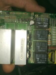
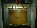
Most of the UPS circuit I have seen ,has four relays and transformer with three coils on primary side.
How they drive the battery charge using these relays ?

11072014571.jpg
11072014570.jpg
 

What are all those power transistors doing?. Using your DVM, check out where the battery connection is going. I would have thought that the relays are used for tap changing BUT there is a stabiliser that accounts for the actual voltage into the battery.
Frank
 

Status
Not open for further replies.

Similar threads

Part and Inventory Search

Welcome to EDABoard.com

Sponsor

Back
Top