Continue to Site

Welcome to EDAboard.com

Welcome to our site! EDAboard.com is an international Electronics Discussion Forum focused on EDA software, circuits, schematics, books, theory, papers, asic, pld, 8051, DSP, Network, RF, Analog Design, PCB, Service Manuals... and a whole lot more! To participate you need to register. Registration is free. Click here to register now.

[SOLVED] Why the body of PMOS output a current when source and body connect together ?

Status
Not open for further replies.

mpig09

Full Member level 4
Joined
Aug 26, 2005
Messages
232
Helped
8
Reputation
16
Reaction score
2
Trophy points
1,298
Location
Taipei
Activity points
2,810
Hi all:

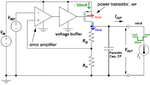
I am design a Capless LDO.
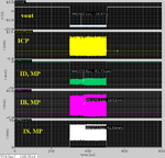
When I check the load regulator of the LDO,
the simulation result is strange:
the output voltage is negative value
when the load from light load to heavy load.
Please reference the attached file.

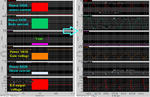
After check the current of the Power MOS (MP) during light load to heavy load,
The simulation shows the body outputs a current when the source and body are connect together.
On the other hand, remove the parasitic cap (CP), the LDO is work normal.

Based on the simulation result, I have some questions?
1. Is the simulation result correct (with/without CP)?
2. the cap how to cause the body of MP output a current?

Could anyone help me ?

Thanks.
mpig
 

Attachments

  • LDO.png
    LDO.png
    56.1 KB · Views: 124
  • LDO_sim.png
    LDO_sim.png
    31.3 KB · Views: 121

Hi,

First thing is not to connect a ideal current source load. I suppose your LDO is not able to supply the current requested by the current source and hence tries to take the output voltage to -20v. How much is your Cp? Is the stability proper under DC load conditions of 50mA?
 

The results are pretty meaningless without knowing the gate voltage and the detail current waveforms. The shown waveforms suggest average values that are probably not real.

As already mentioned, the current source should be diode clamped to avoid negative output voltages. Apart from unplausible simulation results, the main problem is instability which is most likely caused by missing or unsuitable compensation. It has to be solved first.
 

Hi yuvan:

1. the cp is 50pF
2. The loop is stable when the load is 50mA
(for res load or current source, the loop are stable)

------------------------------------------------

Hi FvM:

So I add a diode to serial with current source first?

------------------------------------------------
The compensation method is nested Miller cap.
I will re-post the LDO and other simulation result asap.

Thanks for your reply.
mpig
 

A series diode will hardly clamp the current source. A parallel diode should do the trick.

It may be a case of dynamic instability (slew-rate induced).

Referring to the original question, as long as the substrate junction isn't forward biased, you won't see an average (DC) substrate current. I guess you'll see that there's no DC, just an asymmetrical current pulse waveform with zero average. Did you already zoom into the waveforms?
 

Hi FvM :

1. A parallel diode should do the trick.
==>I will try it.

2. The average of body current is not zero.
3. slew rate ! I can't understand clearly.
I think the slew rate will cause vout or Iout change slowly.
If you have any idea, could you share to me?

Thanks.
mpig
 

Attachments

  • LDO_sim_gate_voltage.png
    LDO_sim_gate_voltage.png
    91.1 KB · Views: 97

Hi,
For MP, there is a pn junction from drain to body, since the drain has already dropped to -10V, this pn junction may have already been broken (not sure about your supply, but it seems to be larger than 13v)

From the current plot, it shows that drain current is provided by channel current (from Source)+body pn junction(from Body), the switching may be caused by on/off of body diode

Btw, whats your rising/falling time of the current load? Maybe the situation is caused by fast load switching. If so, this simulating shall not happen in real world
 

Hi, just try giving slow (relatievely) changing load of 0-->50mA. check if the oscillations are still there. Large signal oscillations are generally due to the slew. As you have mentioned if the slew makes the system slower then it's typically looks like a higher order system and thus instability.
 

HI FvM and yuvan:

1. I add a diode that parallel with the current source and CP, the simulation result is correct.
2. based on your reply "as long as the substrate junction isn't forward biased, you won't see an average (DC) substrate current."
==>I add a diode that connect between source and body of PMOS, the simulation result will correct.
3. After I remove the Cap, the simulation result is correct.

Based on the three simulation results I guess the cause :
1. when the output current change too fast, so the LDO doesn't response,
so the current source gets the current from cap.
2. because the cap doesn't have enough charge, and the current source needs 50mA (heavy load)
it cause the vout drop.

But I can't understand the output voltage will drop to negative value.
When I increase the step time of light load to heavy load, the result is correct too.
Does my design have a hidden problems?

Very thanks your help.

Thanks.
mpig
 

This is a general problem in Capless Arch. You cannot vouch for fast load change. I guess there would be a spec for the load current profile. ACtually the arch you have chosen is generally used for De-cap LDO's. For the capless one, you need an additional fast loop which controls the gate of the PT apart from the main/slower loop or the compensation mech can be implemented to do this. Nested miller (as you have mentioned) is not a efficient way of stabilizing a capless LDO, although you get proper (DC load) stability. Try implementing miliken arch or someother of that sort.

One more thing, if you remove your output cap (50pF), you seem to be getting proper results. Based on this I would assume, the poles are swapping for some intermediate load condition. So, may be first check for differnt load currents (DC) (let say 10u, 100u, 1m, ...50mA) the stability. I think somewhere in the intermediate load your LDO is unstable.
 

Hi yuvan:

Do you mean 1. remove cap
2. set fixed load current of LDO
to check the stability?

Thanks.
mpig
 

Yes, but do it with & without the cap. Change DC load and check for stability for some intermediate conditions and not only extreme load conditions.
 

Hi yuva:

I check the stability from 50mA to 1mA (step is 2.5mA)
the PM, min is 80.

Thanks for your suggestion to check it.

mpig
 

Hi all:

Does my problem is the response of LDO too slow?

Thanks.
mpig

- - - Updated - - -

Hi all:

The transient time of load regulation is suit for ldo?
I set 1us from light load to heavy load, the output voltage of ldo
is a negative value.

But I increase to 3us, the output voltage is correct.

Could anyone give me a suggestion of transient time?

Thanks.
mpig
 

see, there is no global transient time defined, rather it's defined by the load circutary which gets connected. So, get the specification for that. And yes, seeing you simulation results it seems load regulation is slow. And as I have mentioned previously, you cannot expect the load regulation to be better without any fast transient loop--->which generally is followed for Capless arch.
 

Hi yuvan:

Thanks for your reply.

I will try to enhance the slew rate of LDO.

mpig
 

I have implemented a new capless structure that based on
"A capacitor-less low drop-out voltage regulator with fast transient response" by Robert Jon Milliken.

When the step time of the load current is 1us (1mA -->50mA or 50mA --> 1mA), the output voltage will not be a negative value when the load
from light load to heavy load.

But when the step time is slower than 1us, the output voltage will be a
negative value.

Thanks for everyone's help.

mpig
 

Status
Not open for further replies.

Part and Inventory Search

Welcome to EDABoard.com

Sponsor

Back
Top