Continue to Site

Welcome to EDAboard.com

Welcome to our site! EDAboard.com is an international Electronics Discussion Forum focused on EDA software, circuits, schematics, books, theory, papers, asic, pld, 8051, DSP, Network, RF, Analog Design, PCB, Service Manuals... and a whole lot more! To participate you need to register. Registration is free. Click here to register now.

Extending the lower range of the spectrum analyzer?

Status
Not open for further replies.

neazoi

Advanced Member level 6
Joined
Jan 5, 2008
Messages
4,119
Helped
13
Reputation
26
Reaction score
15
Trophy points
1,318
Location
Greece
Activity points
36,918
Hello,
I have a Tek 491 SA with a coverage from 10MHz and up.
Since I would like to analyze frequencies less than 10MHz (VLF/LW/MW/SW), I would like to know how this can be done without altering internal circuits of the SA.

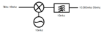
One way I am thinking is to use an upconverter composed of a mini circuits SRA-6 mixer and a 10MHz crystal LO, so that the entire 3KHz-10MHz band (3khz is the lower RF limit of SRA-6) is converted to 10.003MHz-20MHz out from the mixer, which can be fed into the SA RF input port. A HPF ensures that only the added signals pass through and the double balanced mixer minimizes the LO signal leakage. That way, the SA dial will directly read the RF signal frequency, for example a 1MHz RF signal will be read by the SA dial as 11MHz.
How accurate in terms of frequency or amplitude linearity could this solution be? (the Tek 491 is an old instrument anyway). The fact that a single frequency LO is used should lead to high linearity, affected only by the linearity of the SRA-6.

Are there any suggestions or other ways you can think of?
 

Attachments

  • Untitled.png
    Untitled.png
    5.4 KB · Views: 99
Last edited:

We usually want a low pass in the input, to avoid alias signals.

If your input frequency range is up to 10MHz, and the LO is at 10MHz, you can't differentiate between 10MHZ input signal and 10MHz LO feedthrough. User a higher LO frequency, e.g. 20MHz.

The TEK 491 resolution bandwidth isn't made for low frequency operation, but 1kHz/div might still be useful.

The frequency stability (drift & readout accuracy) of your TEK 491 isn't made for such low frequency operations. Readout is accurate to +/-2 MHz and frequency stability is specified as +/-10kHz and temperature drift +/- 5KHz/°C.
 
  • Like
Reactions: neazoi

    neazoi

    Points: 2
    Helpful Answer Positive Rating
Very correct issues.
So the schematic will become as the attached one.

We usually want a low pass in the input, to avoid alias signals.
Where are these signals come from?

The TEK 491 resolution bandwidth isn't made for low frequency operation, but 1kHz/div might still be useful.
This is mainly a problem on the low <10khz range indeed, but it is better than nothing.

The frequency stability (drift & readout accuracy) of your TEK 491 isn't made for such low frequency operations. Readout is accurate to +/-2 MHz and frequency stability is specified as +/-10kHz and temperature drift +/- 5KHz/°C.
Hmmm that is a problem, I might find it difficult to tune below 100khz or so. Maybe some phase locking of the internal LO can be done (1mhz markers), since the SA supports this. Any ideas?

Oh, and some other issue I have not thought, the conversion loss of the mixer, might be a problem, although the SA is quite sensitive and NF is not much of a problem in such low frequencies.
 

Attachments

  • Untitled.png
    Untitled.png
    6.3 KB · Views: 99
Last edited:

Where are these signals come from?

Looks fine now. The input LPF is just to reject frequencies in your input signal which might be downconverted to the 20-30MHz range, or leak into the IF.

The IF BPF is optional in your design: your spectrum analyzer is selective and "has the filter built in".

Hmmm that is a problem, I might find it difficult to tune below 100khz or so. Maybe some phase locking of the internal LO can be done (1mhz markers), since the SA supports this. Any ideas?

No, I am not familiar enough with the 491. Many years ago, I had used the 492 for 24GHz design work, but didn't need additional frequency stability back then.
 
  • Like
Reactions: neazoi

    neazoi

    Points: 2
    Helpful Answer Positive Rating
Because this is a Spectrum Analyzer application, that requires high front-end linearity, I would go even further with the design.
SBL, SRA, and almost all the diode mixers are very sensitive to the IF port termination, is good to place a diplexer at the IF port, before the high-pass filter.
The attached one provides low insertion loss and very good return loss.
In this way everybody would be happy. The mixer that see good return loss for most of the mixing products, and also the high-pass filter which see perfect 50 ohms on the mixer side.
The S21 characteristic of the diplexer have a kind of band-pass characteristic, which would reject even further unwanted mixing products.

7533834500_1402675069.gif
 
  • Like
Reactions: neazoi

    neazoi

    Points: 2
    Helpful Answer Positive Rating
its not so easy. Lets say you upconverted a 2 MHz input to 300 MHz, then down converted it to 20 MHz. Your first LO would convert your input to 302 and 298 MHz, and the LO of 300 MHz would be there too. So when you downconverted to 20 MHz, you will see unwanted spurs at 18, 20, and the actual desired signal at 22 MHz.

You can try to filter the unwanted spurs, but because they are so close to the LO, it will be hard to do.
 
  • Like
Reactions: neazoi

    neazoi

    Points: 2
    Helpful Answer Positive Rating
its not so easy. Lets say you upconverted a 2 MHz input to 300 MHz, then down converted it to 20 MHz. Your first LO would convert your input to 302 and 298 MHz, and the LO of 300 MHz would be there too. So when you downconverted to 20 MHz, you will see unwanted spurs at 18, 20, and the actual desired signal at 22 MHz.
You can try to filter the unwanted spurs, but because they are so close to the LO, it will be hard to do.
Now I am losing it. In your example, I am saying to upconvert say 2MHz to 22MHz with a LO of 20MHz. That's it, no second conversion.
The main products will be 20+2=22MHz and 20-2=18MHz. The 20MHz HPF at the mixer output should filter the 18MHz out.
Well, the reality is that this filter can never be very steep, so some signal will pass through, and the situation becomes worse as you go down in RF input frequency. In fact the 20MHz HPF is not needed at all. The unwanted mixer products will appear on the SA to move at opposite directions to the wanted products. Moreover, these unwanted products will move from 20MHz down to 10MHz as RF is increased, but the wanted ones, will move from 20MHz to 30MHz and therefore directly measured by subtracting 20MHz from the actual dial reading.

The 491, having an internal harmonics LO for the microwave bands WILL in fact use this reverse direction of the harmonic mixer products to determine the different microwave bands.

In a receiver situation the unwanted harmonics of the converter could cause a problem, but in this application I do not see how it could affect the measurements and the correct determination of the received frequency.

- - - Updated - - -

Because this is a Spectrum Analyzer application, that requires high front-end linearity, I would go even further with the design.
SBL, SRA, and almost all the diode mixers are very sensitive to the IF port termination, is good to place a diplexer at the IF port, before the high-pass filter.
The attached one provides low insertion loss and very good return loss.
In this way everybody would be happy. The mixer that see good return loss for most of the mixing products, and also the high-pass filter which see perfect 50 ohms on the mixer side.
The S21 characteristic of the diplexer have a kind of band-pass characteristic, which would reject even further unwanted mixing products.

7533834500_1402675069.gif

Which frequencies is this diplexer sending to the load and which ones to the output?
 

no in this type of system you upconvert to a fixed IF frequency, like 300, send it thru a saw filter there, then downconvert to a frequency your S/A will work at. You would need a tunable 1st LO.

This is the method that they use in cable tv tuners, where they need to send a 50 to 900 MHz signal into the IF of the cable converter box.
 
  • Like
Reactions: neazoi

    neazoi

    Points: 2
    Helpful Answer Positive Rating
The diplexer is fine for the 20MHz to 30MHz range, because you are going to use this front-end adapter only for the 3kHz to 10Mhz (as you mentioned above).
The return loss (S11) of this diplexer has very wide frequency range, so high order of mixing products will be absorbed and not reflected back to the mixer. The insertion loss (S21) is low only in 20MHz to 30MHz range, which is fine for this application.
thank you very much!
 

I am curious about the diplexer, where should be the missed port 3? At Which freq band?
Thanks.
 

In this situation (diplexer with 2 ports) port 3 is virtually (internally) connected to a 50 ohms load.
This kind of two-port diplexer is used mainly after diode or FET-type switching mixers, to improve linearity.

3-ports DIplexers (made by a LPF and a HPF) are usually used in front-ends to separate bands, when DUplexers are used to separate RX and TX.

For a better understanding of the circuit I am attaching an old document that I just found.
 

Attachments

  • diplexer.pdf
    415.4 KB · Views: 96
Last edited:
Hi, Vfone,
thank you very much. I faced the same issue when I designed Weather Radar LNA.
I had to tradeoff pad and NF.
Thanks for the detail explanation.
 

Status
Not open for further replies.

Part and Inventory Search

Welcome to EDABoard.com

Sponsor

Back
Top